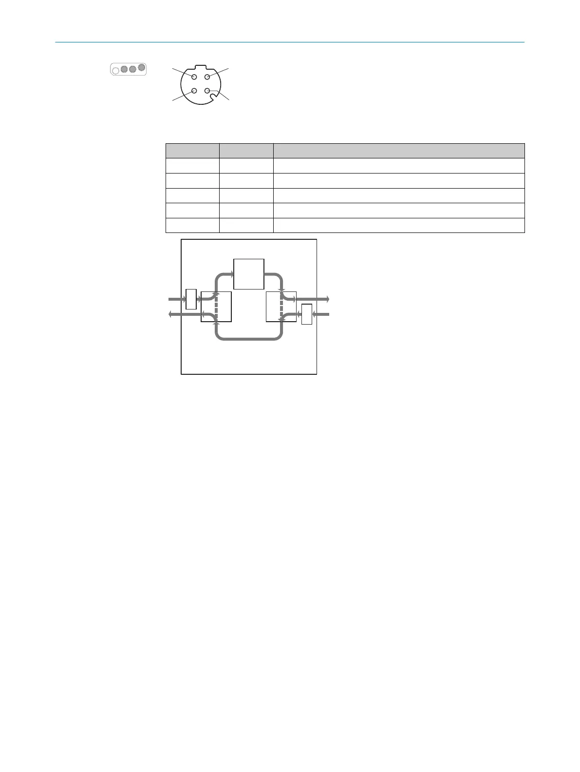
Figure 54: Network pin assignment (M12 female connector, 4-pin, D-coding)
Table 6: Network pin assignment
Pin Designation Function
1 TX+ Send data +
2 RX+ Receive data +
3 TX– Send data -
4 RX– Receive data -
Thread SH Shielding
Figure 55: Internal topology of EtherCAT connections
1
EtherCAT processing unit
2
Auto forwarder
3
Loopback function (the data follow the dashed arrow when no network cable with a
f
unctioning remote station is attached at the connection.)
Complementary information
T
he processing direction is from the XF1 connection to the XF2 connection. That is, in
normal operation the device receives the data from the controller on XF1 and sends the
outgoing data on XF2.
6 ELE
CTRICAL INSTALLATION
82
O P E R A T I N G I N S T R U C T I O N S | microScan3 – EtherCAT® 8025220/1L9Q/2023-08-14 | SICK
Subject to change without notice