When the startup process is finished, the status LEDs and the display show the current
oper
ational status.
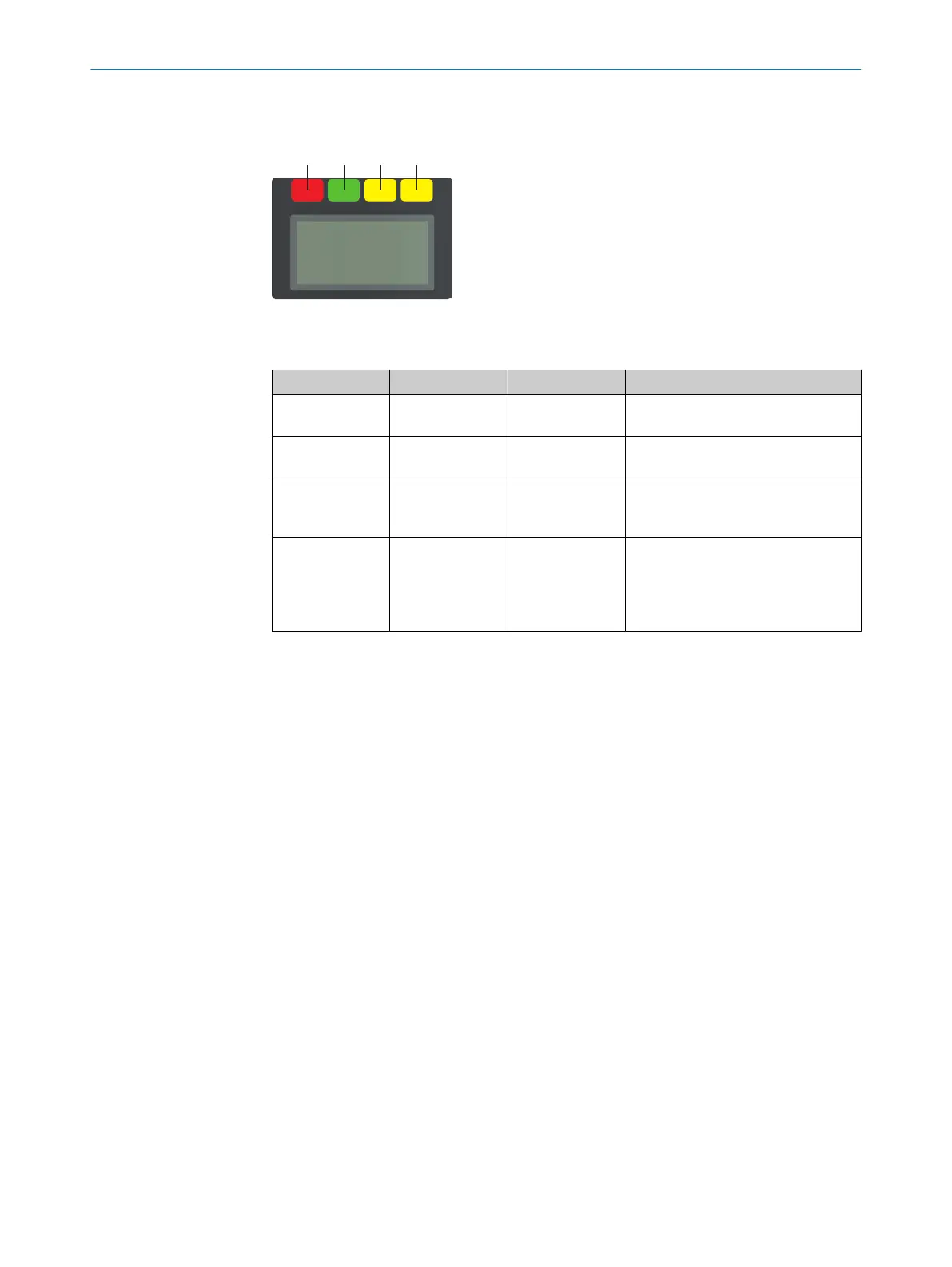
Figure 80: Status LEDs
T
able 18: Status LEDs
Number Function Color Meaning
1
OFF state Red Lights up red when at least one
s
afety output is in the OFF state.
2
ON state Green Lights up green when at least one
safety output is in the ON state.
3
Warning field Yellow Lights up yellow if an object is
detected in at least one warning
field.
4
Restart interlock Yellow Setup with reset: Flashes if the
r
estart interlock has been triggered.
Configuration with automated restart
after a time: Lights up while the con‐
figured time to restart expires.
The OFF state and ON state light emitting diodes can be found in multiple locations on
t
he device. 3 additional sets are arranged in pairs on the base of the optics cover. So
the LEDs can also be seen in many cases when it is not possible to see the display, e.g.
due to the mounting situation or because it is hidden from the operator’s position.
The device has different LEDs for every network interface. These network LEDs are
located below the display.
More information about what the LEDs mean and the symbols and information shown
on the display:see "Troubleshooting", page 148.
8.4 Check during commissioning and modifications
The thorough check is intended to ensure that the safety functions are fulfilling their
planned pur
pose and whether persons are being adequately protected.
►
Carry out the checks specified in the test plan of the manufacturer of the machine
and the operating entity.
8 C
OMMISSIONING
134
O P E R A T I N G I N S T R U C T I O N S | microScan3 – EtherCAT® 8025220/1L9Q/2023-08-14 | SICK
Subject to change without notice