safety outputs switch to the OFF state. In Safety Designer, you can define the
t
olerance band around the reference contour in both directions (near and far).
°
For high availability, setting both the positive tolerance band (far) and the
negative tolerance band (near) to the TZ value is recommended. (TZ = toler‐
ance zone of the safety laser scanner, see "Data sheet", page 160.)
°
The tolerance band must not be too wide. The reference contour field must
detect a deviation from the reference contour before access to the hazardous
point occurs next to the protective field. Deviations may occur due to changes
in position or orientation.
°
If the reference contour represents the edge of the protected opening, the
sum of the negative and positive tolerance bands must not be greater than
the resolution of the protective field.
°
If the reference contour does not represent the edge of the protected open‐
ing, the sum of the negative and positive tolerance bands must not be
greater than the projection.
•
You can define a number of contours in the reference contour field and therefore
monitor various areas in the environment.
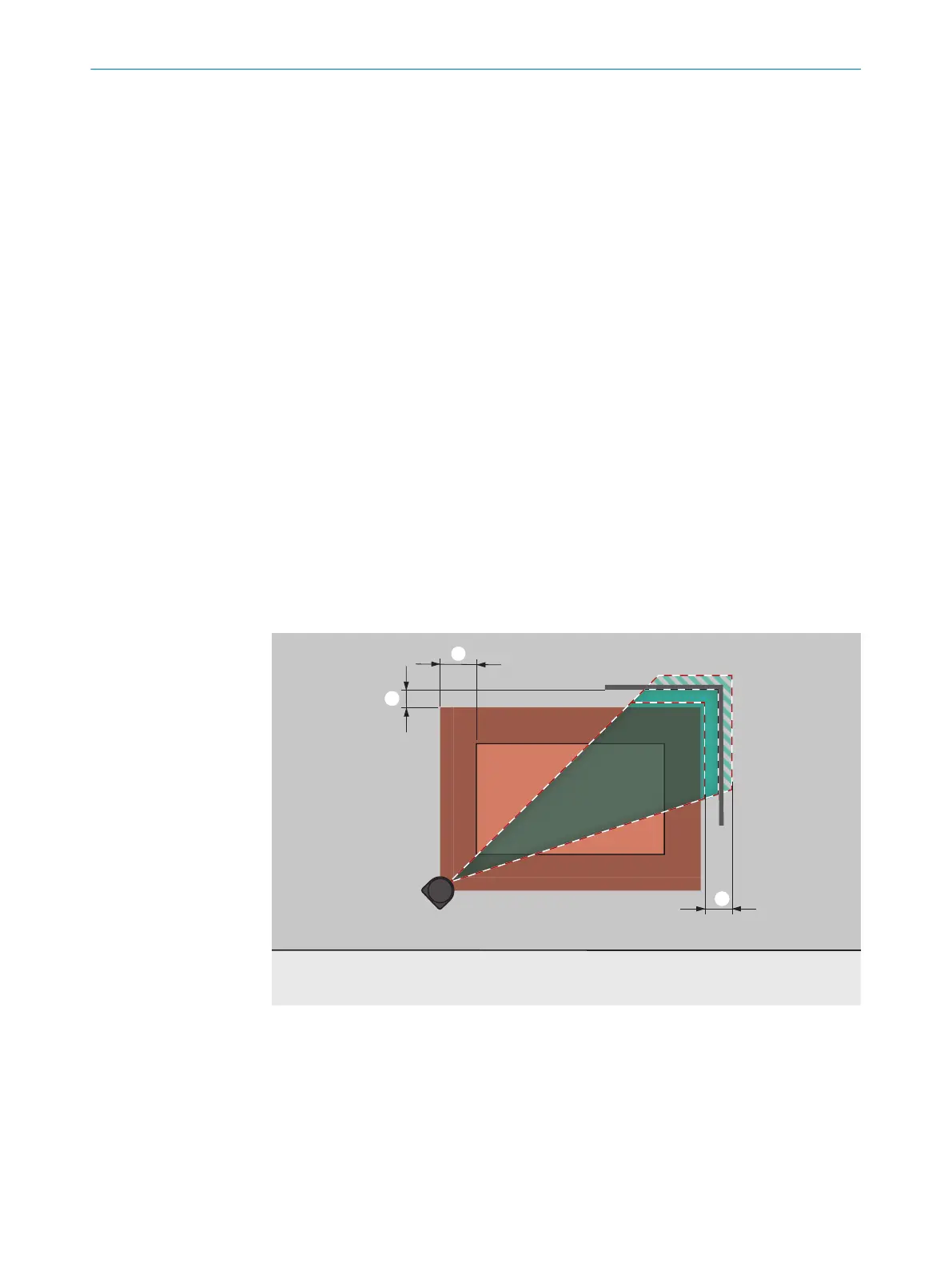
Protective field and reference contour field for hazardous point protection
The protective field must be larger than the protected opening. The required overrun (o)
is calculated using the following formula:
o ≥ (2 × TZ) – d
Where:
•
o = overrun of the protective field over the opening
•
TZ = tolerance zone of the safety laser scanner, see "Data sheet", page 160
•
d = set resolution
Figure 24: Overrun of the protective field in front of an opening
1
Tolerance band of the reference contour field
2
Distance of the protective field from the contour, to ensure availability
3
o = overrun of the protective field over the opening
PROJECT PLANNING 4
8025220/1L9Q/2023-08-14 | SICK O P E R A T I N G I N S T R U C T I O N S | microScan3 – EtherCAT®
31
Subject to change without notice