EasyManuals Logo

SICK EtherCAT microScan3 User Manual

SICK EtherCAT microScan3
208 pages
To Next Page IconTo Next Page
To Previous Page IconTo Previous Page
Page #118 background imageLoading...
Page #118 background image
7.14 Monitoring cases
Overview
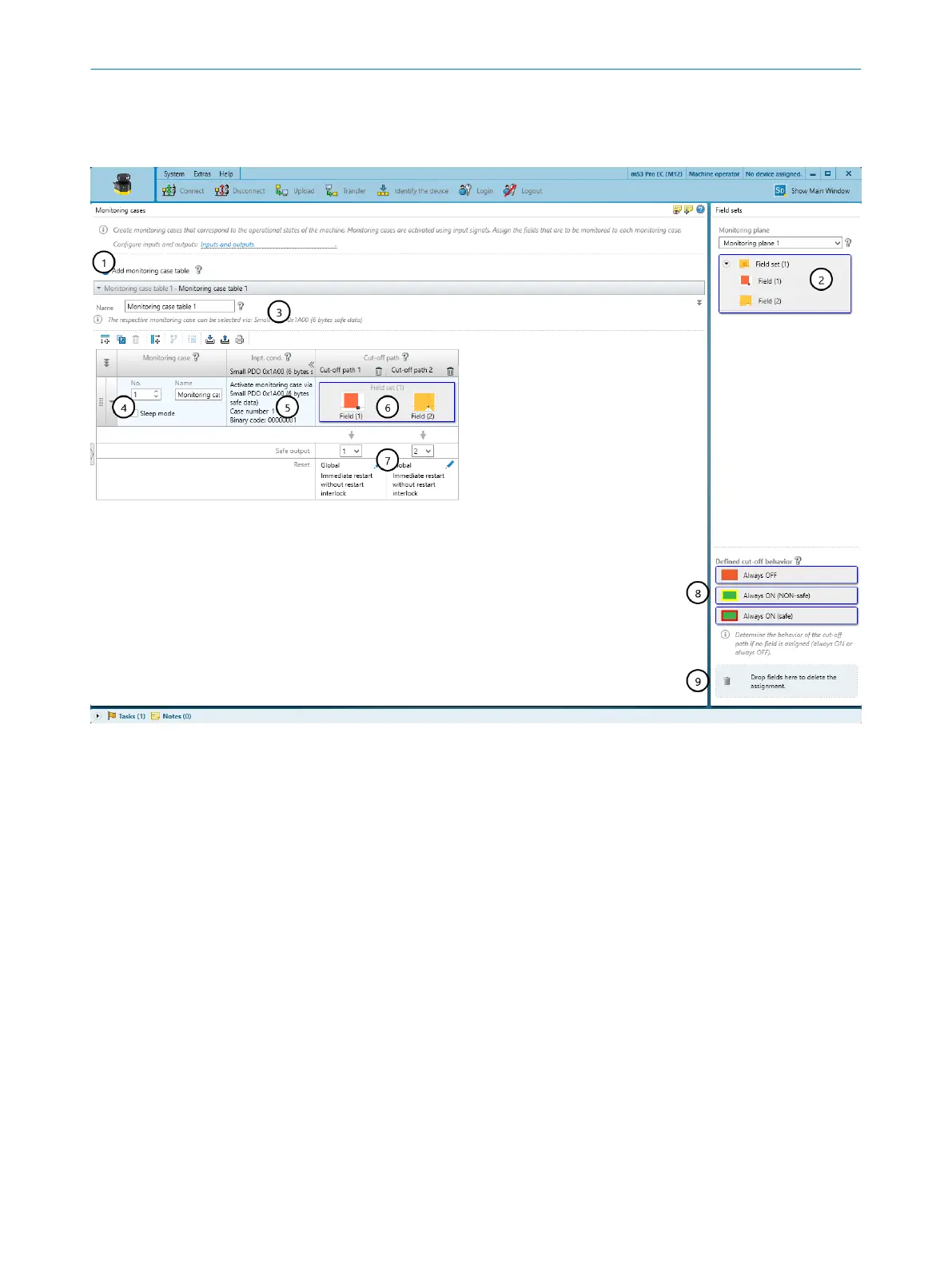
Figure 73: Monitoring cases
1
Add monitoring case table
2
Configured field sets
3
Settings for the whole monitoring case table
4
Settings for the individual monitoring case
5
Input conditions for a monitoring case
6
Field set in the monitoring case and in the cut-off path
7
Cut-off paths
8
Areas for defined cut-off behavior
9
Remove field set from a monitoring case
In the monitoring case editor, you can also define the monitoring cases with input
condit
ions and assign the field sets.
Further topics
"Monit
oring case", page 21
7.14.1 Settings for monitoring case tables
Name
In t
he Name field, enter a name for the monitoring case table that is as descriptive as
possible.
7 C
ONFIGURATION
118
O P E R A T I N G I N S T R U C T I O N S | microScan3 – EtherCA 8025220/1L9Q/2023-08-14 | SICK
Subject to change without notice

Table of Contents

Questions and Answers:

Question and Answer IconNeed help?

Do you have a question about the SICK EtherCAT microScan3 and is the answer not in the manual?

SICK EtherCAT microScan3 Specifications

General IconGeneral
Scanning angle275°
InterfacesEtherCAT
Protection classIP65
Supply voltage24 V DC
Resolution for protective field30 mm
Operating voltage24 V DC
Scanning range5.5 m
Number of fields128
Number of monitoring cases128
Response time30 ms
Operating temperature0 °C to 50 °C
Field of applicationIndustrial safety
Light sourceInfrared laser, 905 nm
Connection typeM12
Weight1.2 kg

Related product manuals