Figure 82: Status LEDs
T
able 19: Status LEDs
Number Function Color Meaning
1
OFF state Red Lights up red when at least one
s
afety output is in the OFF state.
2
ON state Green Lights up green when at least one
s
afety output is in the ON state.
3
Warning field Yellow Lights up yellow if an object is
detected in at least one warning
field.
4
Restart interlock Yellow Setup with reset: Flashes if the
restart interlock has been triggered.
Configuration with automated restart
after a time: Lights up while the con‐
figured time to restart expires.
The OFF state and ON state light emitting diodes can be found in multiple locations on
t
he device. 3 additional sets are arranged in pairs on the base of the optics cover. So
the LEDs can also be seen in many cases when it is not possible to see the display, e.g.
due to the mounting situation or because it is hidden from the operator’s position.
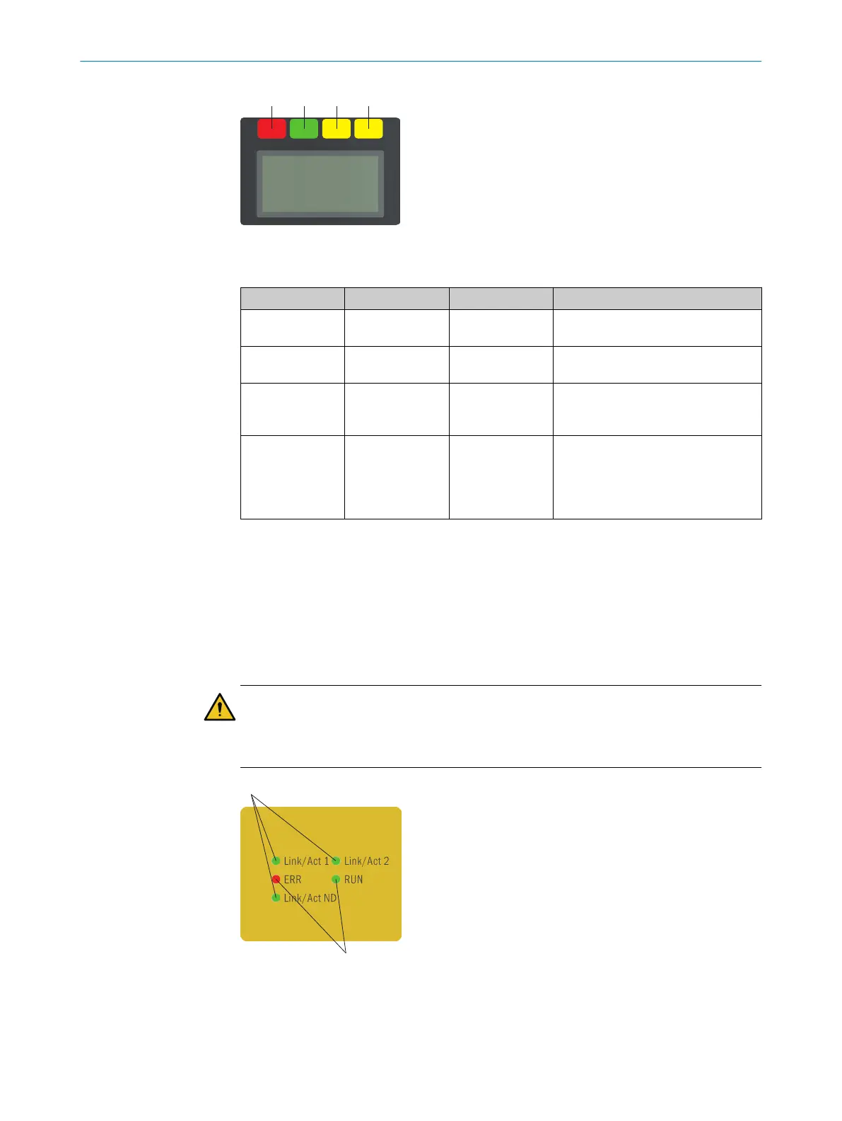
9.3.2 Network LEDs
The device has different LEDs for every network interface. These network LEDs are
located below the display.
CAUTION
T
he network LEDs are only used for diagnostic purposes and are not safety-relevant.
The safety function of the device is not impaired even if the status indicators are
incorrectly displayed or fail.
Figure 83: Network LEDs
9 OPERATION
136
O P E R A T I N G I N S T R U C T I O N S | microScan3 – EtherCAT® 8025220/1L9Q/2023-08-14 | SICK
Subject to change without notice