6.2.1 microScan3 – EtherCAT®
Table 4: System plug and connections: microScan3 – EtherCAT®
Safety laser scanner Suitable system plug Plug connector
microScan3 – EtherCAT®
MICSX-BANNEZZZ1 (part number: 2081021)
•
XD1: v
oltage supply, page 81
•
XF1: network connection for
EtherCAT IN, page 81
•
XF2: network connection for
EtherCAT OUT , page 81
•
XF3: Ethernet for data output,
configuration and diagnostics,
page 81
•
Alternative FE connection,
page 81
6.3 Pin assignment
You will find the pin assignment for the individual plug connectors in the following.
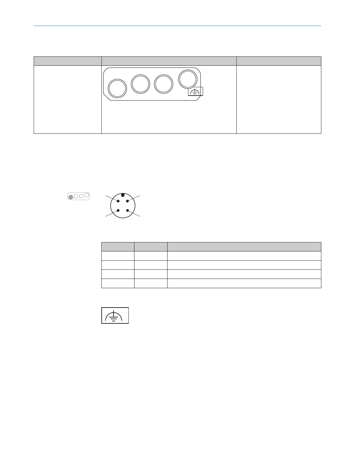
6.3.1 Voltage supply (XD1)
Voltage supply is supplied via a 4-pin, A-coding M12 male connector on the device side.
Figure 52: Pin assignment of the voltage supply (male connector, M12, 4-pin, A-coded)
Table 5: Pin assignment of the voltage supply
Pin Designation Function
1 24V DC 24VDC supply voltage
2 nc Not connected
3 0 V DC Supply voltage 0 V DC
4 FE Functional earth/shield
6.3.2 Alternative FE connection
Figure 53: Alternative FE connection
S
crew connection of the alternative FE connection
•
Screw: M5 × 12
•
Tightening torque: 3.5Nm to 5.0Nm
Suitable cable lugs
•
Forked cable lug or ring cable lug
•
Width ≤10mm
•
Hole diameter for screw: typically 5.2mm
6.3.3 Network connection for EtherCAT (XF1, XF2) and Ethernet for data output, configuration and diag‐
nost
ics (XF3)
On the device side, Ethernet and EtherCAT are connected via 4-pin, D-coded M12
f
emale connectors. The pin assignment corresponds to IEC 61918, Appendix H.
ELECTRICAL INSTALLATION 6
8025220/1L9Q/2023-08-14 | SICK O P E R A T I N G I N S T R U C T I O N S | microScan3 – EtherCAT®
81
Subject to change without notice