EasyManuals Logo

SICK EtherCAT microScan3 User Manual

SICK EtherCAT microScan3
208 pages
To Next Page IconTo Next Page
To Previous Page IconTo Previous Page
Page #114 background imageLoading...
Page #114 background image
7.12.8 Defining global geometry
Overview
Y
ou draw field geometries and non-monitored areas as global geometry. The global
geometry affects all protective fields and warning fields.
Table 14: Defining global field geometry
Edit field editor settings
Procedure
1.
Click on the Edit field editor settings tool.
2. Activate the Use global geometry checkbox.
3. In the Field set area, select > Global Geometry.
4. Draw a global field geometry.
5. If applicable, draw non-monitored areas with the Mask areas tool.
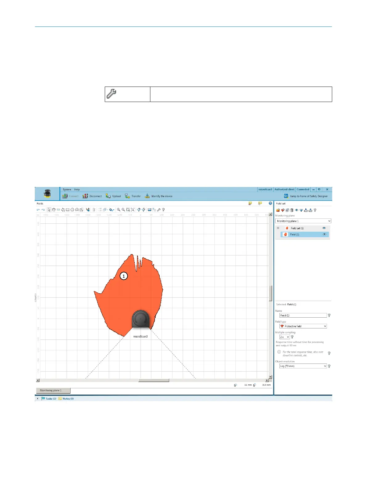
7.12.9 Enable propose field
Overview
Figure 71: Enable propose field
1
Proposal for a protective field
You can have a protective field or warning field suggested by Safety Designer.
7 C
ONFIGURATION
114
O P E R A T I N G I N S T R U C T I O N S | microScan3 – EtherCA 8025220/1L9Q/2023-08-14 | SICK
Subject to change without notice

Table of Contents

Questions and Answers:

Question and Answer IconNeed help?

Do you have a question about the SICK EtherCAT microScan3 and is the answer not in the manual?

SICK EtherCAT microScan3 Specifications

General IconGeneral
Scanning angle275°
InterfacesEtherCAT
Protection classIP65
Supply voltage24 V DC
Resolution for protective field30 mm
Operating voltage24 V DC
Scanning range5.5 m
Number of fields128
Number of monitoring cases128
Response time30 ms
Operating temperature0 °C to 50 °C
Field of applicationIndustrial safety
Light sourceInfrared laser, 905 nm
Connection typeM12
Weight1.2 kg

Related product manuals