DC link components
8.1 Braking Module Booksize
SINAMICS S120 Combi
142 Manual, Edition 07/2012, 6SL3097-4AV00-0BP3
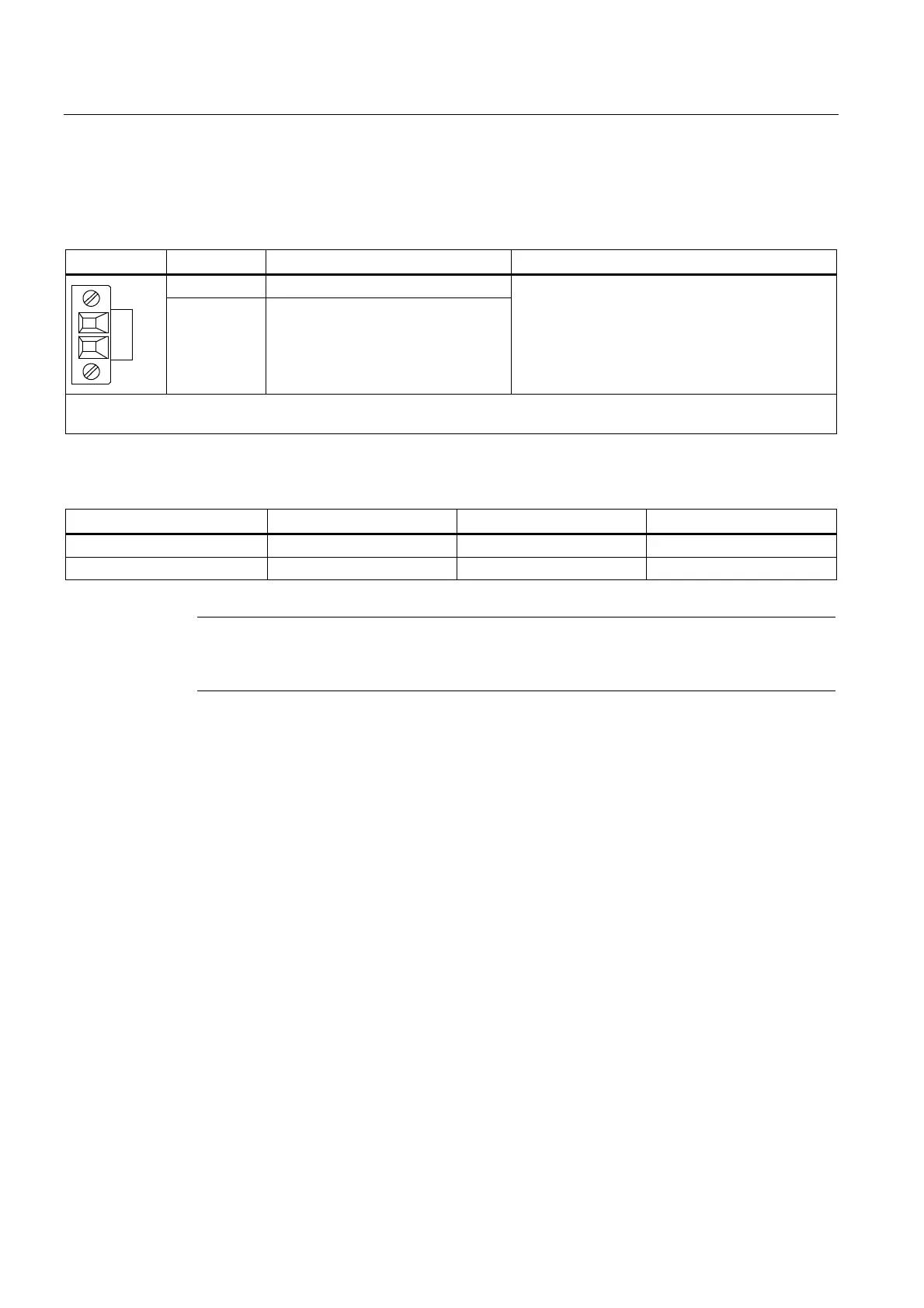
8.1.3.2 X1 braking resistor connection
Table 8- 1 X1 braking resistor connection
Terminal Designation Technical specifications
1 Braking resistor connection R1
5 5
2 Braking resistor connection R2
Continued-short-circuit-proof
Max. connectable cross-section: 4 mm
2
Type: Screw terminal 4 (see Chapter "Control cabinet installation and EMC / connection system")
Table 8- 2 Braking resistors without a thermostatic switch for Braking Modules
Braking resistor R in Ω P
N
in kW P
max
in kW
6SN1113-1AA00-0DA0 17 0.3 25
6SL3100-1BE31-0AA0 5.2 1.5 100
Note
For detailed technical information on the braking resistors, see the chapter titled "DC link
components/braking resistors".

 Loading...


