Encoder system connection
11.2 Sensor Module External SME20
SINAMICS S120 Combi
Manual, Edition 07/2012, 6SL3097-4AV00-0BP3
217
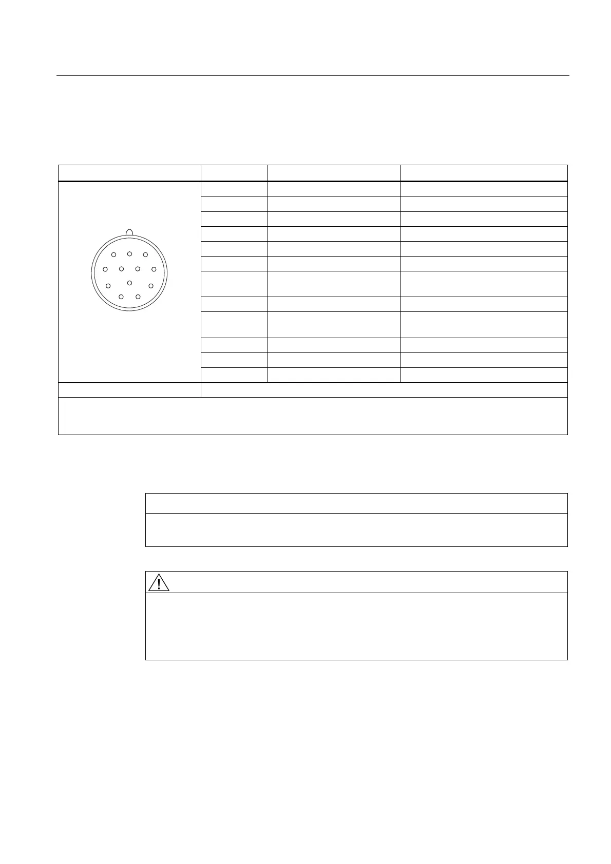
11.2.3.4 Encoder system interface
Table 11- 7 Encoder system interface SME20
Pin Signal name Technical specifications
1 B* Inverse incremental signal B
2 P5 Encoder power supply
3 R Reference signal R
4 R* Inverse reference signal R
5 A Incremental signal A
6 A* Inverse incremental signal A
7 -Temp
1)
Temperature sensor connection
2)
KTY84-1C130 or PTC
8 B Incremental signal B
9 +Temp
1)
Temperature sensor connection
2)
KTY84-1C130 or PTC
10 M Ground for encoder power supply
11 M Ground for encoder power supply
12 P5 Encoder power supply
Connector kit: 12-pin, order number: 6FX2003-0SA12
Measuring current via temperature sensor connection: 2 mA
Blanking cover for encoder system interface: Pöppelmann GmbH & Co. KG, Lohne,
Order No.: GPN 300 F211
1) These connections do not have protective separation!
2) Connection cable: Order number 6FX8002-2CA88-xxxx
NOTICE
The KTY temperature sensor must be connected with the correct polarity. A sensor
connected up with the incorrect polarity cannot detect if the motor overheats
DANGER
Risk of electric shock!
Only temperature sensors that meet the safety isolation specifications contained in
EN 61800-5-1 may be connected to terminals "+Temp" and "-Temp".
If these instructions are not complied with, there is a risk of electric shock!

 Loading...


