Encoder system connection
11.3 Sensor Module External SME25
SINAMICS S120 Combi
Manual, Edition 07/2012, 6SL3097-4AV00-0BP3
225
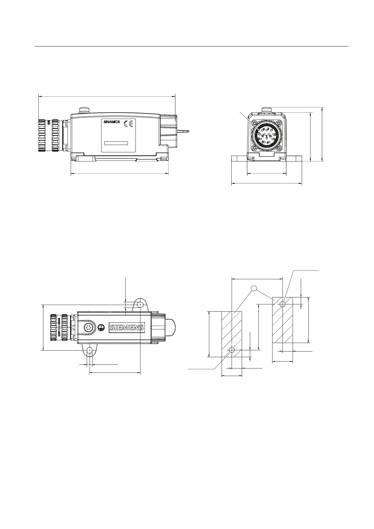
11.3.3 Dimension drawing
60(SLQ
60(SLQ
:LWKRXWFDEOHOXJ
*HQHUDOWROHUDQFHss
Figure 11-11 Dimension drawing of Sensor Module External SME25, all data in mm and (inches),
order number 6SL3055-0AA00-5HA3
11.3.4 Installation
1
01P
01P
① Contact surface
Figure 11-12 Drilling pattern for installing the SME20/SME25
Installation
1. Place the drilling pattern on the mounting surface. Make sure that the contact surface is
bare, unpainted metal.
2. Drill two holes with Ø 5.3 or M5 threaded holes according to the drilling pattern.
3. Fix the Sensor Module to the mounting surface. The tightening torque is 6 Nm.

 Loading...


