Additional system components
10.1 Terminal Module TM54F
SINAMICS S120 Combi
190 Manual, Edition 07/2012, 6SL3097-4AV00-0BP3
10.1.8 Protective conductor connection and shield support
It is always advisable to shield the digital input and output wiring.
The following diagram shows a typical Weidmüller shield connection clamp for the shield
supports.
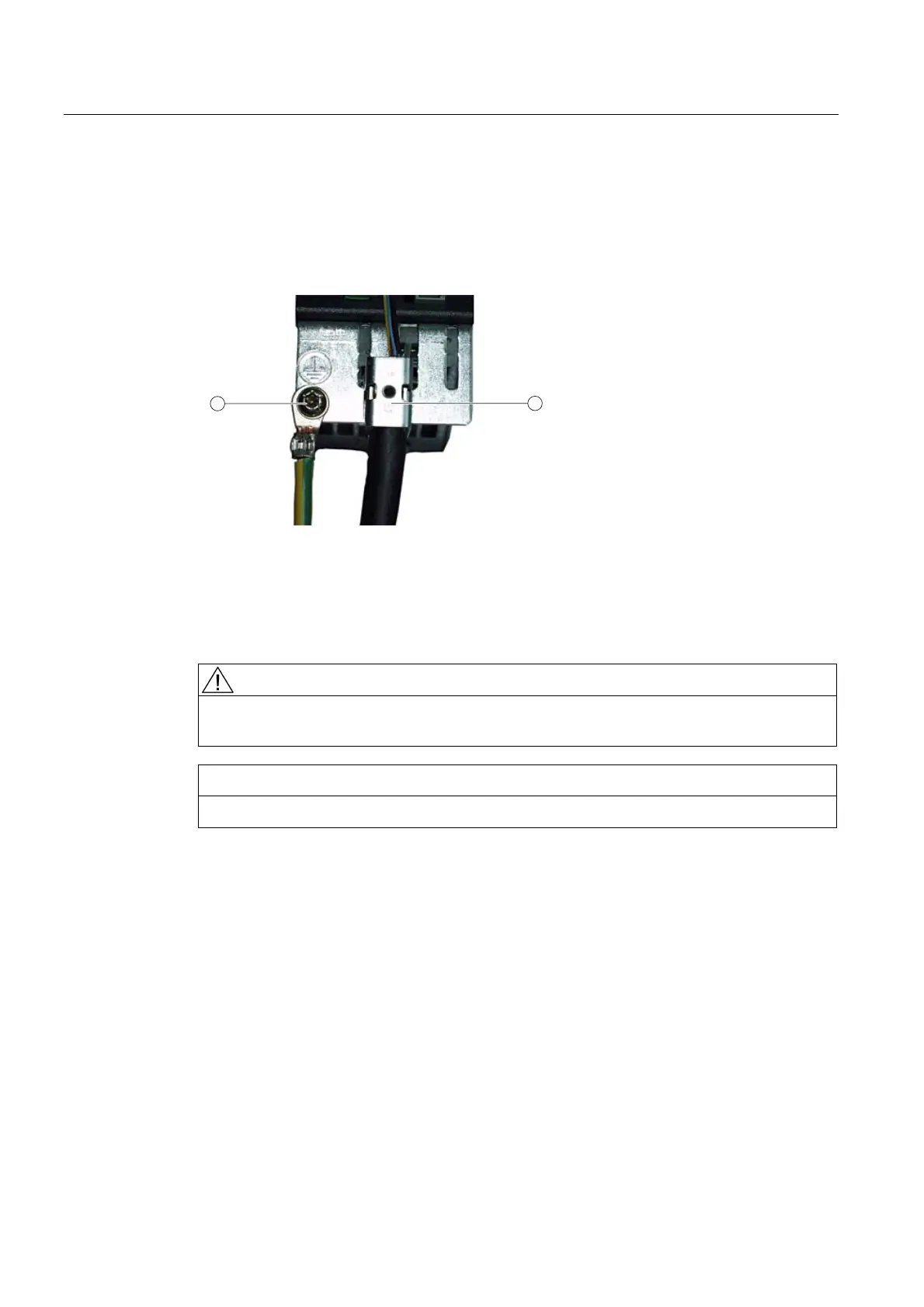
2
1
① Protective conductor connection M4/1.8 Nm
② Shield connection terminal, Weidmüller company, type: KLBÜ CO1, order number:
1753311001
Figure 10-5 Shield support and protective conductor connection
DANGER
If the shielding procedures described and the permissible cable lengths are not observed,
the machine may malfunction.
NOTICE
Only use screws with a permissible insertion depth of 4 - 6 mm.

 Loading...


