Cabinet design and EMC
13.8 Protective connection and equipotential bonding
SINAMICS S120 Combi
Manual, Edition 07/2012, 6SL3097-4AV00-0BP3
255
13.8 Protective connection and equipotential bonding
Protective connections
The S120 Combi is designed for use in control cabinets with a protective conductor
connection.
The protective conductor connection of the S120 Combi must be connected to the protective
conductor connection of the control cabinet as follows:
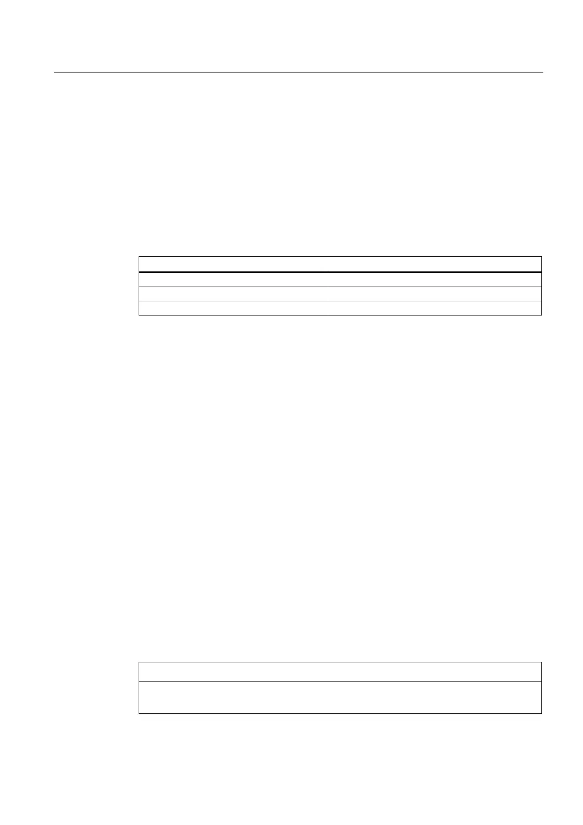
Table 13- 14 Cross-section for copper protective conductors
Line supply cable in mm
2
Protective connection in mm
2
copper
Up to 16 mm
2
The same as the line supply cable
From 16 mm
2
to 35 mm
2
16 mm
2
From 35 mm
2
0.5 * line supply cable
For materials other than copper, the cross-section should be increased so that as a
minimum, the same conductivity is attained.
All plant and machine parts must be incorporated in the protective concept.
The protective ground connection of the motors used must be established through the motor
cable. For EMC reasons, these protective ground connections should be connected at the
S120 Combi.
In order to maintain the EMC limit values, the S120 Combi drive line-up - including the
expansion axes and DC link components - must be arranged together on a bare metal
mounting plate. The mounting plate serves as an equipotential bonding surface. This means
that no additional equipotential bonding is required within the drive line-up. The mounting
plate must be connected to the protective conductor connection of the control cabinet
through a low impedance.
Equipotential bonding
A mounting plate serves simultaneously as an equipotential bonding surface. This means
that no additional equipotential bonding is required within the drive line-up.
If a common bare metal mounting plate is not available, then an equally good equipotential
bonding must be established using cable cross-sections as listed in the table above or as a
minimum with the same conductivity.
When mounting components on standard mounting rails, the equipotential bonding data
listed in the table apply. If only smaller connection cross-sections are permissible at the
components, then the largest possible cross-section should be used, e.g. 6 mm
2
for SMC.
These requirements also apply to distributed components located outside the control
cabinet.
NOTICE
Non-observance of the above guidelines on equipotential bonding can lead to faults on the
fieldbus interfaces or to malfunction of the devices.

 Loading...


