DC link components
8.2 Control Supply Module CSM
SINAMICS S120 Combi
Manual, Edition 07/2012, 6SL3097-4AV00-0BP3
161
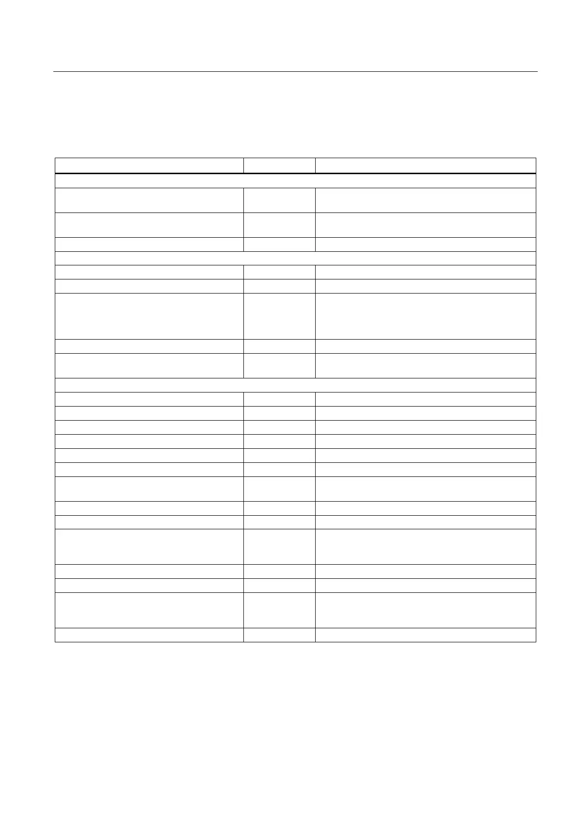
8.2.8 Technical data
Table 8- 13 Technical data
6SL3100-1DE22-0AA1
Input data, AC input
Line voltage
Line frequency
V
AC
Hz
3-ph. 380 - 480 V
AC
± 15 %
45 to 66
Rated input current
Rated value (at V
E rated
)
A
AC
≤ 2
Starting current inrush A
AC
≤ 28 at > 5 ms
Input data, DC input
Rated input voltage V
DC
600
Input voltage range V
DC
300 - 882
DC link voltage
(continuous input voltage)
V
DC
430 to 800
300 - 430 < 1 min
800 - 853 < 1 min
853 - 882 < 10 s
Supply current (at 600 V) A
DC
1.1
Overvoltage trip
Undervoltage trip
V
DC
V
DC
> 882
280 ± 3 %
Output data
Rated output voltage V
A rated
: V
DC
24 - 28.8 V
Rated output current I
A rated
1)
A
DC
20
Rated output power P
A rated
W 520
Overcurrent limitation for short-circuit A
DC
approx. 23
Surge suppression V < 35
Current carrying capacity of the 24 V busbar A
DC
20
Residual ripple (clock frequency approx. 50
kHz)
mV
pp
< 100
Cycle peaks (bandwidth 20 MHz) mV
pp
< 200
Power loss ride-through (at 400 V
AC
) ms 5
Power loss
2)
Line
DC link
W
70
65
Efficiency % >83
Cooling method Internal air cooling
Max. ambient temperature
Without derating
With derating as of 26 V output voltage
°C
°C
≤40
>40 to 55
Weight kg 4.8
1) Upwards 40°C, a linear derating of the output current for 26 V output voltage and higher must be observed
2) For an overview, see the power loss tables in the chapter titled Control cabinet installation

 Loading...


