Additional system components
10.1 Terminal Module TM54F
SINAMICS S120 Combi
Manual, Edition 07/2012, 6SL3097-4AV00-0BP3
177
NOTICE
For the digital inputs DIx+ to function, the reference potential must be connected to input
DIx- in each case.
This is achieved by:
1) routing the ground reference of the digital inputs as well, or
2) a jumper between DIx and terminal M1.
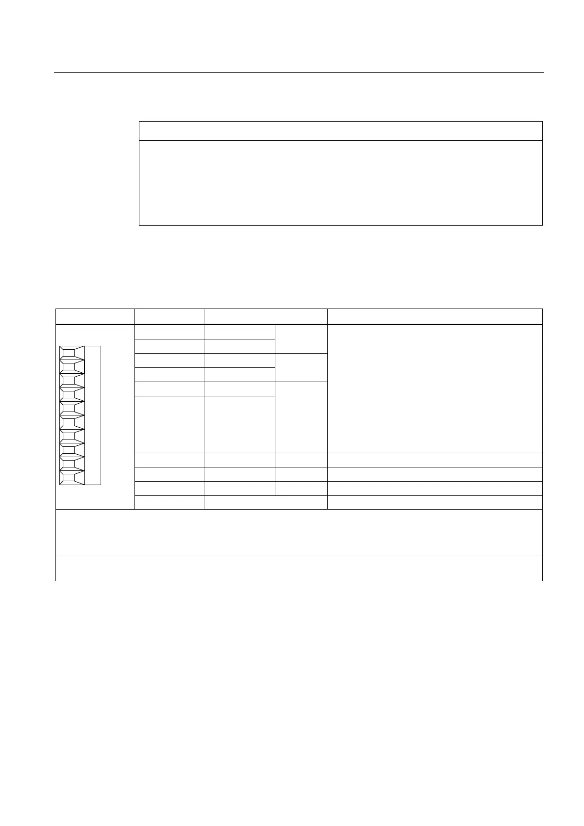
10.1.3.6 X522 fail-safe digital inputs
Table 10- 6 Terminal block X522
Terminal Designation
1)
Technical specifications
1 DI 4
2 DI 5+
F-DI 2
3 DI 6
4 DI 7+
F-DI 3
5 DI 8
6 DI 9+
F-DI 4
Voltage: -3 V to +30 V DC
Typical current consumption: 3.2 mA at 24 V
Electrical isolation:
Reference potential, refer to terminals 7, 8, 9, 10
All digital inputs are electrically isolated.
Level (incl. ripple)
High level: 15 V to 30 V
Low level: -3 V to +5 V
Input delay:
2)
For "0" → "1": 30 μs (100 Hz)
For "1" to "0": 60 μs (100 Hz)
7 DI 5- F-DI 2 Reference potential for DI 5+
8 DI 7- F-DI 3 Reference potential for DI 7+
9 DI 9- F-DI 4 Reference potential for DI 9+
10 M1 Reference potential for DI 4, DI 6 and DI 8
An F-DI comprises a digital input and a 2nd digital input where, in addition, the cathode of the optocoupler is fed-out.
F-DI 2 = terminals 1, 2 and 7
F-DI 3 = terminals 3, 4 and 8
F-DI 4 = terminals 5, 6 and 9
Max. connectable cross-section: 1.5 mm²
Type: Screw terminal 1 (see "Control cabinet installation and EMC/Connection system")
1) DI: Digital input, F-DI: Fail-safe digital input
2) Pure hardware delay

 Loading...


