Encoder system connection
11.3 Sensor Module External SME25
SINAMICS S120 Combi
Manual, Edition 07/2012, 6SL3097-4AV00-0BP3
223
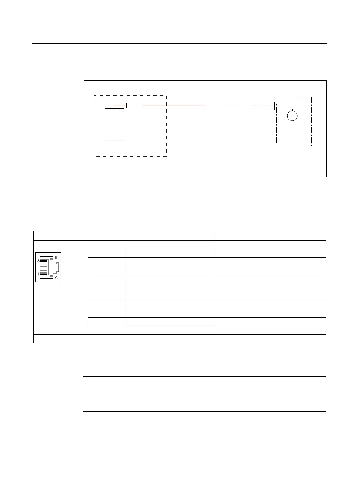
11.3.2.2 Connection example
(QFRGHUFDEOH
&RQWUROFDELQHW
'LUHFWHQFRGHUV\VWHP
*
'5,9(&/L4
FDEOH
338
'0(
60(
Figure 11-10 Connection of a direct encoder system via a Sensor Module External (SME)
11.3.2.3 DRIVE-CLiQ interface
Table 11- 9 DRIVE-CLiQ interface
Pin Signal name Technical specifications
1 TXP Transmit data +
2 TXN Transmit data -
3 RXP Receive data +
4 Reserved, do not use
5 Reserved, do not use
6 RXN Receive data -
7 Reserved, do not use
8 Reserved, do not use
A + (24 V) Power supply
B M (0 V) Electronics ground
Connector type RJ45 socket
Current consumption max. 0.25 A
The blanking cover for the DRIVE-CLiQ port is included in the scope of delivery.
Blanking covers (50 pieces) Order number: 6SL3066-4CA00-0AA0
Note
Only MOTION-CONNECT DRIVE-CLiQ cables may be used for connections. The maximum
cable length is 100 m for MOTION-CONNECT 500, and 75 m for MOTION-CONNECT
800PLUS cables.

 Loading...


