Cabinet design and EMC
13.6 24 V DC supply
SINAMICS S120 Combi
Manual, Edition 07/2012, 6SL3097-4AV00-0BP3
245
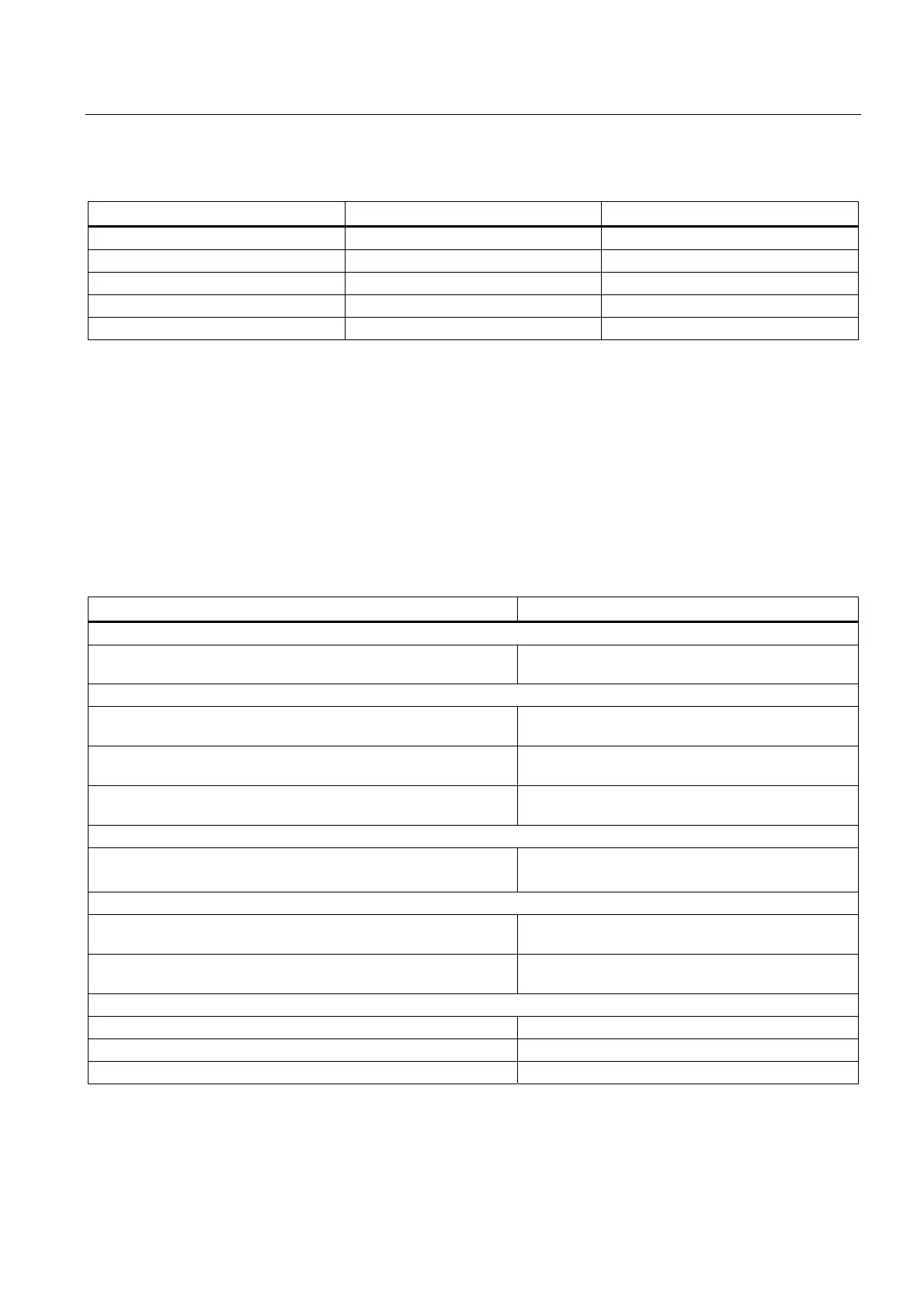
Table 13- 2 MCBs by core cross-section and temperature
Core cross-section Max. value up to 40 °C Max. value up to 55°C
1.5 mm
2
10 A 6 A
2.5 mm
2
16 A 10 A
4 mm
2
25 A 16 A
6 mm
2
32 A 20 A
24 V busbar 20 A 20 A
The trip characteristic of the MCBs must be selected to match the loads to be protected and
the max. current provided by the power supply unit in the event of a short-circuit.
13.6.4 Typical 24 V current consumption of the components
A separate 24 V power supply must be used for the SINAMICS S120 drive line-up.
The following table can be used to calculate the 24 V DC power supply. The values for
typical current consumption are used as a basis for configuration.
Table 13- 3 Overview of 24 V DC current consumption
Component Typical current consumption [A
DC
]
Controller
SINUMERIK 828D - PPU without load
SINUMERIK 828D - PPU with full load (USB, handwheel...)
1.2
2.5
Sensor Modules
SMC20
without/with encoder system
0.20 / 0.355
SME20
without/with encoder system
0.15 / 0.25
SME25
without/with encoder system
0.15 / 0.25
Terminal Modules
TM54F (without digital outputs, without DRIVE-CLiQ)
Per digital output/DRIVE-CLiQ
0.2
0.5
Additional system components
DMC20 (without DRIVE-CLiQ)
per DRIVE-CLiQ
0.15
0.5
DME20 (without DRIVE-CLiQ)
per DRIVE-CLiQ
0.15
0.5
S120 Combi 3 axes Power Module
16 kW / 18 A / 5 A / 5 A 1.5
16 kW / 24 A / 9 A / 9 A 1.5
20 kW / 30 A / 9 A / 9 A 1.5

 Loading...


