S120 Combi Power Modules
3.8 Electrical connection
SINAMICS S120 Combi
88 Manual, Edition 07/2012, 6SL3097-4AV00-0BP3
Cable cross-section in mm
2
A in mm and (inches)
4 x 1.5 55
+3
(2.17
+0.12
)
4 x 2.5 55
+3
(2.17
+0.12
)
4 x 4 55
+3
(2.17
+0.12
)
4 x 6 55
+2
(2.17
+0.08
)
4 x 10 55
+2
(2.17
+0.08
)
3.8.1 Line supply cable
Shielded MOTION-CONNECT 500 and 800 line supply cables are recommended in order to
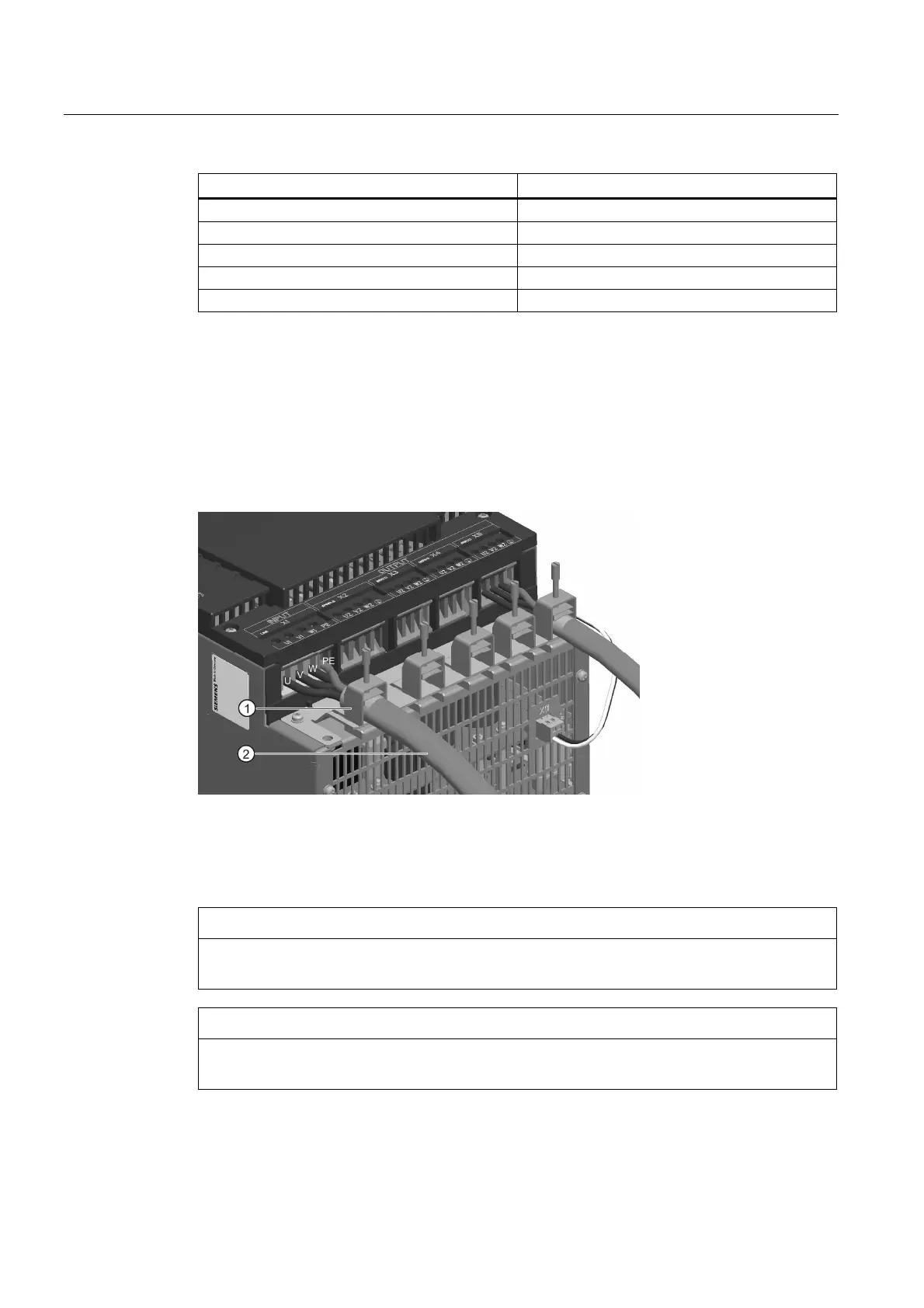
maintain the EMC limit values. The line supply cable is connected at interface X1 (INPUT).
The single cores of the cable are labeled with U, V, W and PE. Cables are connected at the
S120 Combi corresponding to the terminal labeling.
The cable shield should be connected and fixed using the shield clamp.
1 Shield connection clamp
2 Line supply cable
Figure 3-18 Line supply cable connected at the S120 Combi
NOTICE
The shield clamp does not provide strain relief. Strain relief for the power cable must be
separately realized using a suitable measure.
CAUTION
When using unshielded power cables, the shield clamp must not be used, as otherwise the
unshielded single cores could be damaged.

 Loading...


