S120 Combi Power Modules
3.3 Interface description
SINAMICS S120 Combi
70 Manual, Edition 07/2012, 6SL3097-4AV00-0BP3
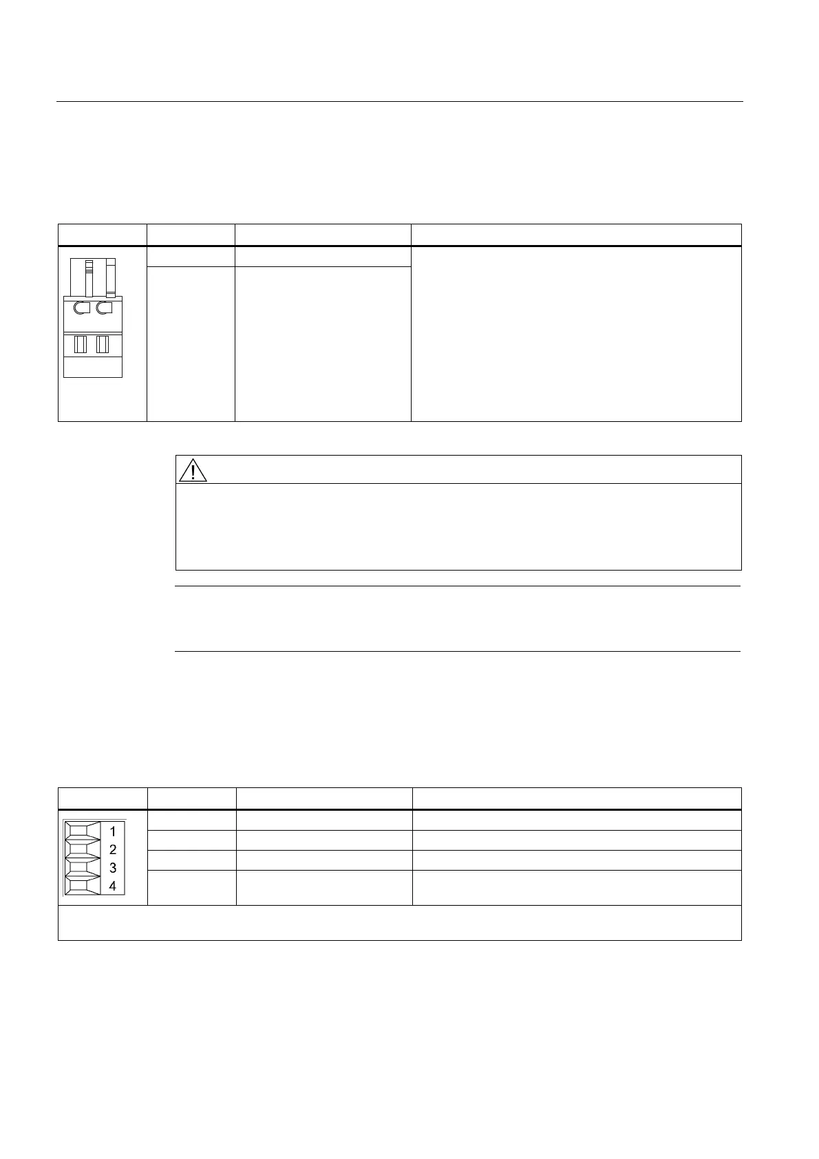
3.3.4 X11 brake connection
Table 3- 7 Brake connection X11
Terminal Designation Technical specifications
BR + Brake connection +
Connector
BR - Brake connection -
Voltage 24 V DC
max. load current 1 A
min. load current 0.1 A
Max. connectable cross-section 2.5 mm
2
Type: Spring-loaded terminal 1 (see Chapter "Control
cabinet installation and EMC / connection system")
The brake connector is part of the prefabricated cable.
WARNING
Only protective extra-low voltages (PELV) must be connected to all connections and
terminals between 0 and 48 V DC.
The voltage tolerances of the motor holding brakes (24 V ± 10%) must be taken into
account.
Note
The motor brake must be connected via connector X11. The BR- cable must not be
connected directly to electronics ground (M).
3.3.5 X12/X13 fan connection
Table 3- 8 X12/X13 connection of the external fan unit
Terminal Designation Technical specifications
1 Ground
2 Fan monitoring
3 +24 V Current-carrying capacity, 2 x 1 A or 1 x 2 A
4 Ground
Max. connectable cross-section: 1.5 mm
2
Type: Screw terminal 1 (see Chapter "Control cabinet installation and EMC / connection system")

 Loading...


