Cabinet design and EMC
13.9 Note on control cabinet cooling
SINAMICS S120 Combi
Manual, Edition 07/2012, 6SL3097-4AV00-0BP3
261
If air conditioners are used, the relative air humidity of the expelled air increases as the air in
the air conditioner cools and may exceed the dew point. If the relative humidity of the air
entering the SINAMICS equipment is over 80% for an extended period of time, the insulation
in the equipment may fail to function properly due to electrochemical reactions (see Chapter
"System overview"). Using air baffle plates, for example, you must ensure that the cold air
expelled from the air conditioner mixes with warm air in the cabinet before it enters the unit.
This reduces the relative air humidity to uncritical values.
13.9.3 Dimensioning Climate Control Equipment
Cabinet manufacturers provide calculation programs for selecting climate control equipment.
It is always necessary to know the power loss of the components and equipment installed in
the cabinet.
The physical relationship is shown in the following example.
Calculating the thermal power to be dissipated: q = Q - k x A x ΔT
with
q = thermal power that has to be dissipated using a cooling unit [W]
Q = power loss [W]
∆T = difference between the room temperature and the temperature inside the cabinet [K]
k = heat transfer coefficient, e.g. sheet-steel, painted 5.5 [W/(m
2
* K)]
A = free-standing cabinet surface area [m
2
]
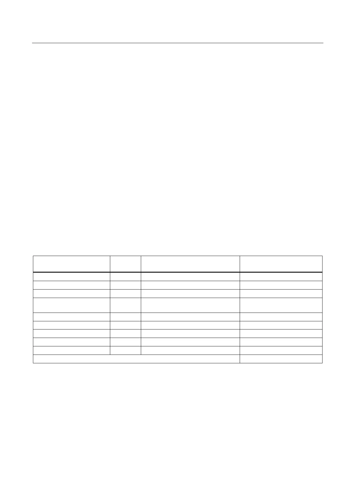
Table 13- 16 Example, calculating the power loss of a drive configuration
Component Number Total power loss [W]
(including electronic losses)
Total power loss [W]
SINUMERIK 828D 1 28 28
Line filter 1 16 16
Line reactor 1 98 98
S120 Combi 3 axes Power
Module 20 kW
1 634 634
Motor Module 9 A 1 100.4 100.4
Motor Module 18 A 1 185.4 185.4
SMC 2 10 20
SITOP 20 1 53 53
Line contactor 1 12 12
Total: 1146.8
Assumption:
free-standing control cabinet surface A = 5 m
2
difference between the room temperature and the temperature inside the control cabinet ∆T
= 10 K
q = 1644 W - 5.5 W / (m
2
K) * 5 m
2
* 10 K = 871.8 W

 Loading...


