Electrically connecting Motor Modules and DC link components
9.4 Connecting an additional component
SINAMICS S120 Combi
172 Manual, Edition 07/2012, 6SL3097-4AV00-0BP3
3. Prepared Motor Modules to connect the DC link busbars
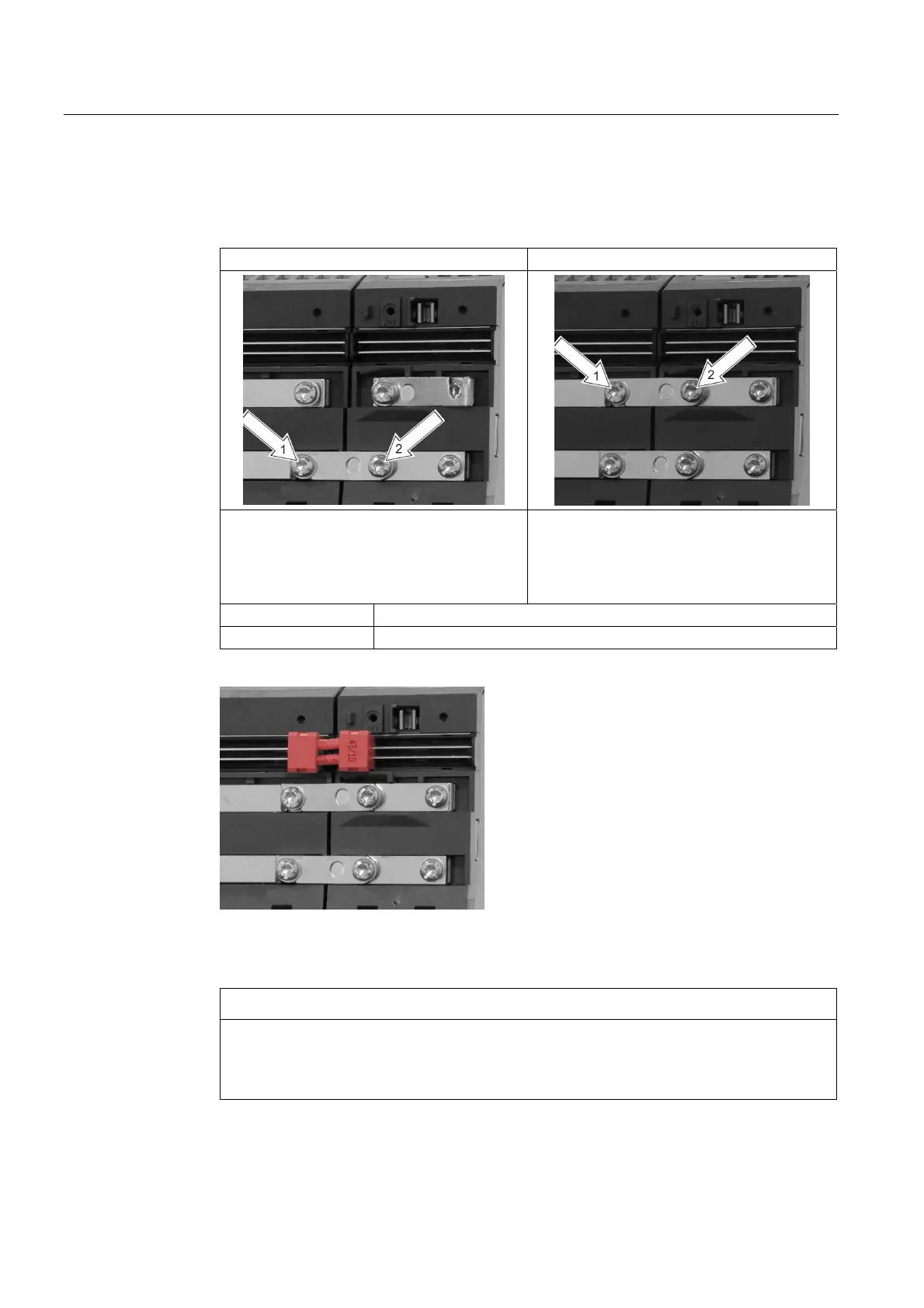
4. Install the lower and upper DC link busbars
Install the lower DC link busbar Install the upper DC link busbar
• Release the screws
• Turn the DC link bridge
• Observe the sequence when tightening the
screws
• Release the screws
• Turn the DC link bridge
• Observe the sequence when tightening the
screws
Screwdriver Torx T20 or slotted 1.2 x 6
Tightening torque 1.8 Nm
5. Installing the red 24 V connector (accessories pack of the component to be connected)
Figure 9-3 Motor Modules with 24 V connector installed
6. Close the protective covers of both components
CAUTION
Before commissioning the drive line-up, it must be ensured, that:
• The DC link side cover is inserted at the outer component (touch protection).
• The protective covers of all of the components are closed.

 Loading...


