Cabinet design and EMC
13.9 Note on control cabinet cooling
SINAMICS S120 Combi
Manual, Edition 07/2012, 6SL3097-4AV00-0BP3
265
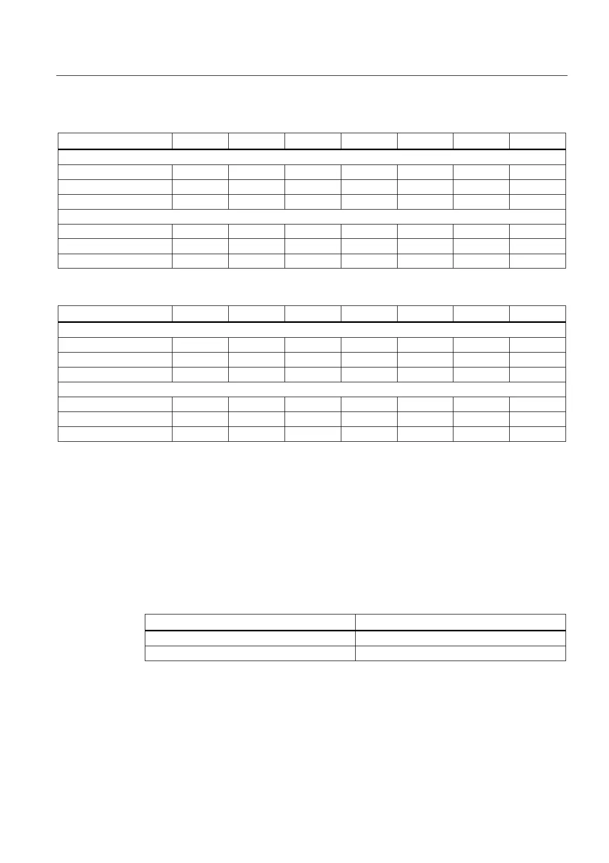
Table 13- 21 Overview of the coefficients to calculate the total power loss P
V
in the partial-load range
Power Module a b IN1 S1 S2 S3 S4
3 axes Power Module
16 kW / 18 A 36 19.2 11.05 7.1 6.5 6.5
16 kW / 24 A 36 19.2 11.2 7.2 7.2 7.2
20 kW / 30 A 36 19.2 11.5 7.3 7.2 7.2
4 axes Power Module
16 kW / 18 A 38.4 19.2 11.05 7.1 7.2 6.5 6.5
16 kW / 24 A 38.4 19.2 11.4 7.2 7.2 7.2 7.2
20 kW / 30 A 38.4 19.2 11.7 7.3 7.7 7.2 7.2
Table 13- 22 Overview of the coefficients to calculate the power loss P
V
in the control cabinet for external cooling
Power Module a b IN1 S1 S2 S3 S4
3 axes Power Module
16 kW / 18 A 36 0 1.95 0.6 0.4 0.4
16 kW / 24 A 36 0 2.1 0.6 0.4 0.4
20 kW / 30 A 36 0 2.03 0.6 0.4 0.4
4 axes Power Module
16 kW / 18 A 38.4 0 1.95 0.6 0.4 0.4 0.4
16 kW / 24 A 38.4 0 2.3 0.6 0.4 0.4 0.4
20 kW / 30 A 38.4 0 2.23 0.6 0.4 0.4 0.4
Losses in the partial-load range for line reactors
The losses of the line reactors in partial-load operation can be calculated using the following
formula:
P
V
= D1 x P1
With:
D1: Coefficient to calculate the power loss
P1: Infeed power [kW]
Table 13- 23 Overview of the coefficients to calculate the power loss P
V
in the partial-load range
Line reactor D1
6SL3100-0EE21-6AA0 (16 kW) 4.7
6SL3100-0EE22-0AA0 (20 kW) 4.9

 Loading...


