Tips
13.9 Configuration of the drive with macros
CNC Part 1 (NCK, PLC, drive)
Commissioning Manual, 11/2006, 6FC5397-2AP10-2BA0
217
Note
The list of DOs involved in process-data exchange is completed by entering a value of
"0". Components that are available, but do not communicate on PROFIBUS, must be
preset to "255".
The list of drive objects is already pre-assigned in the following order by the system upon
initializing the drive (acceptance of topology):
• ALM, first Motor Module …n., CU; e.g., 2-3-4-5-1.
• The assignment allocated by the drive when the topology is accepted must be reviewed
and adapted.
Drive-object numbers
The drive object numbers (DO numbers) can be viewed under "Commissioning > Machine
data > Control Unit MD/Infeed MD/Drive MD" in the component name line. For example, the
name for a Control Unit could be: "DP3.Slave3:CU_003 (1)". The DO number appears inside
the brackets "(…)".
Drive-object assignment
The table below uses the example of a SINAMICS S120 component configuration to
illustrate the drive-object assignment to be made for the drive parameters.
For example, the drive group could be configured as follows:
• One Control Unit (CU)
• one active line module (ALM)
• Three Motor Modules
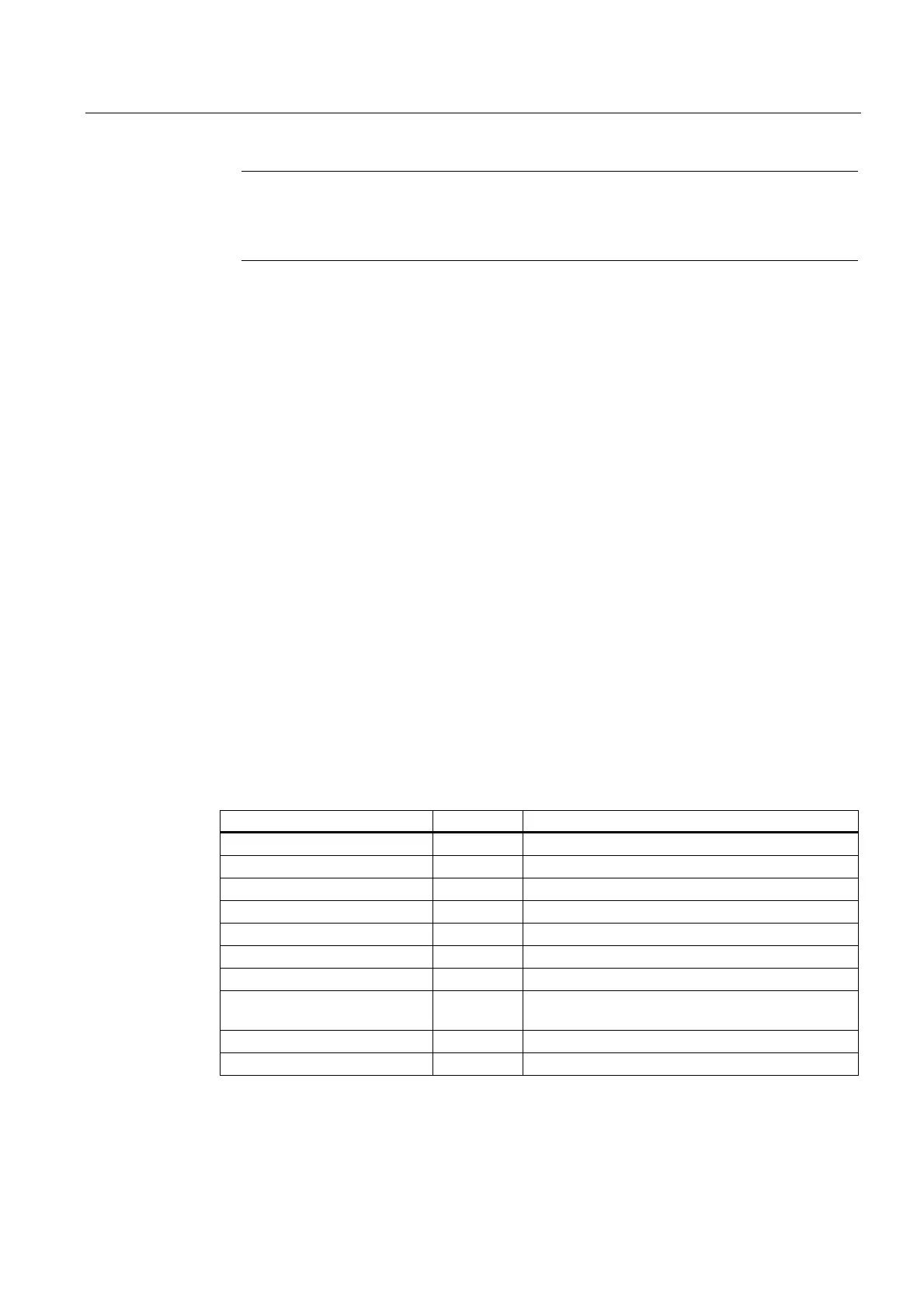
Table 13-1 Assignment of p978[0…9] for infeed with Drive-CLiQ connection
Component Index p978 List of drive objects
1. Motor module 0 3
2. Motor module 1 4
3. Motor module 2 5
not found 3 255
1)
not found 4 255
1)
not found 5 255
1)
CU 6 1
ALM, only if protocol 370 is
available
7 255
1)
not found 8 0
2)
ALM (Standard for SINUMERIK) 9 2
1) Not active
2) End of exchange of PZD