5
Parameters operating area 01/2008
5.2 Tool offset
5
©Siemens AG 2008 All rights reserved.
5-174 SINUMERIK 840Di sl/840D sl/840D Operating Manual HMI-Advanced (BAD) - 01/2008 Edition
Offsets that are not required must be assigned the value 0 (= default
when the offset memory is set up).
The tool offsets can be entered not only via the operator panel front
but also via the data input interface.
For programming offset data, see
/PG/, Programming Guide Fundamentals
5.2 Tool offset
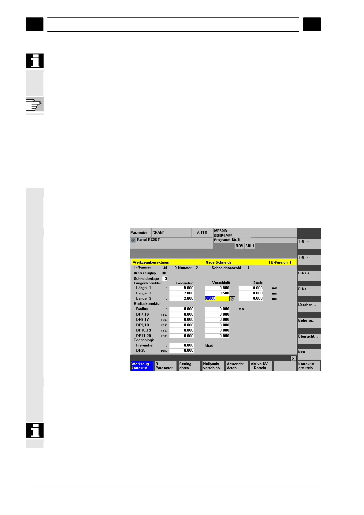
5.2.1 Function and main screen Tool offset
Tool offset data consist of data which describe the geometry, wear,
identification, tool type and the assignment to parameter numbers.
The unit used for the dimensions of the tool is displayed.
The input field is highlighted.
Every offset number contains up to 25 parameters, depending on the
tool type.
The number of parameters shown in the window is that for the tool
type.
The maximum number of offset parameters (T and D numbers) can be
set by means of machine data.

 Loading...


