Functions
2.14 Differential Protection and Its Protected Objects
SIPROTEC, 7UM62, Manual
C53000-G1176-C149-7, Release date 03.2010
102
2.14 Differential Protection and Its Protected Objects
The numerical current differential protection of the 7UM62 is a high speed selective short-circuit protection for
generators, motors and transformers. The individual application can be configured, which ensures optimum
matching to the protected object.
The protected zone is selectively limited by the CTs at its ends.
2.14.1 Differential Protection (ANSI 87G/87M/87T)
The processing of the measured values depends on the way the differential protection is used. This section
discusses first the differential protection function in general, regardless of the type of protected object. A single-
phase system is referred to. Then particularities of individual protected objects are treated.
2.14.1.1 Functional Description
Basic Principle
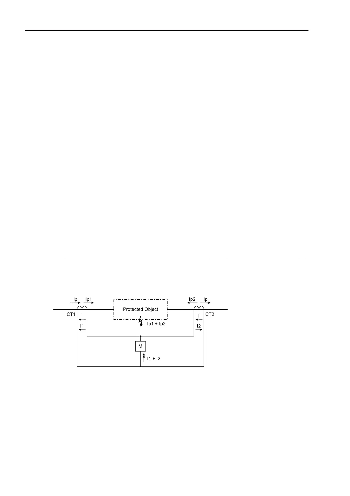
Differential protection systems operate according to the principle of current comparison and are therefore also
known as current balance protection systems. They utilize the fact that in a healthy protected object the current
leaving the protected object is the same as that which entered it (current Ip, dotted in the following figure).
The secondary windings of current transformers CT1 and CT2, which have the same transformation ratio, may
be so connected that a closed circuit is formed. If now a measuring element M is connected at the electrical
balance point, it reveals the current difference. Under undisturbed conditions (e.g. on-load operation) no current
flows in the measuring element. In the event of a fault in the protected object, the summation current
I
p1
+I
p2
flows on the primary side. The currents on the secondary side I
1
and I
2
flow as a summation current I
1
+I
2
through the measuring element M. As a result, the simple circuit shown in the following figure ensures a reliable
tripping of the protection if the fault current flowing into the protected zone (limited by the current transformer)
during a fault is high enough for the measuring element M to respond.
Figure 2-30 Basic Principle of Differential Protection (Single-Phase Representation)
(I
px
= primary current, I
x
= secondary current)

 Loading...


