Functions
2.38 Breaker Failure Protection (ANSI 50BF)
SIPROTEC, 7UM62, Manual
C53000-G1176-C149-7, Release date 03.2010
266
2.38.2 Setting Notes
General
Breaker failure protection is only effective and available if address 170 BREAKER FAILURE is set to Side 1
or Side 2 during configuration. If the function is not required Disabled is set. Address 7001 BREAKER
FAILURE serves to switch the function ON or OFF or to block only the trip command (Block relay).
The current measurement for breaker failure protection can be performed either at side 1 (inputs I
L, S1
) or at
side 2 (inputs I
L, S2
). It is recommended to use the terminal-side set of CTs, i.e. side 1.
Criteria
The parameter 7002 TRIP INTERN serves to select the OFF criterion of an internal pickup. It can be imple-
mented by reading the switching status of the output relay BO12 provided for this (7002 TRIP INTERN = BO12)
or by a logic link created in CFC (= CFC) (Message 1442 „>int. start B/F“). The internal source can also
be completely deactivated (7002 TRIP INTERN = OFF). In this case only external sources have effect.
Note: Be aware that only the potential-free binary output BO12 (relay BO12) can be used for the breaker failure
protection. This means that trippings for the mains breaker (or the particular breaker being monitored) must be
configured to this binary output.
The pickup threshold 7003 CIRC. BR. I> setting of the current criterion applies for all three phases. The
user must select a value ensuring that the function still picks up even for the lowest operating current to be
expected. For this reason, the value should be set at least 10% below the minimum operating current.
However the pickup value should not be selected lower than necessary, as an excessively sensitive setting
risks prolonging the drop-out time due to balancing processes in the current transformer secondary circuit
during switchoff of heavy currents.
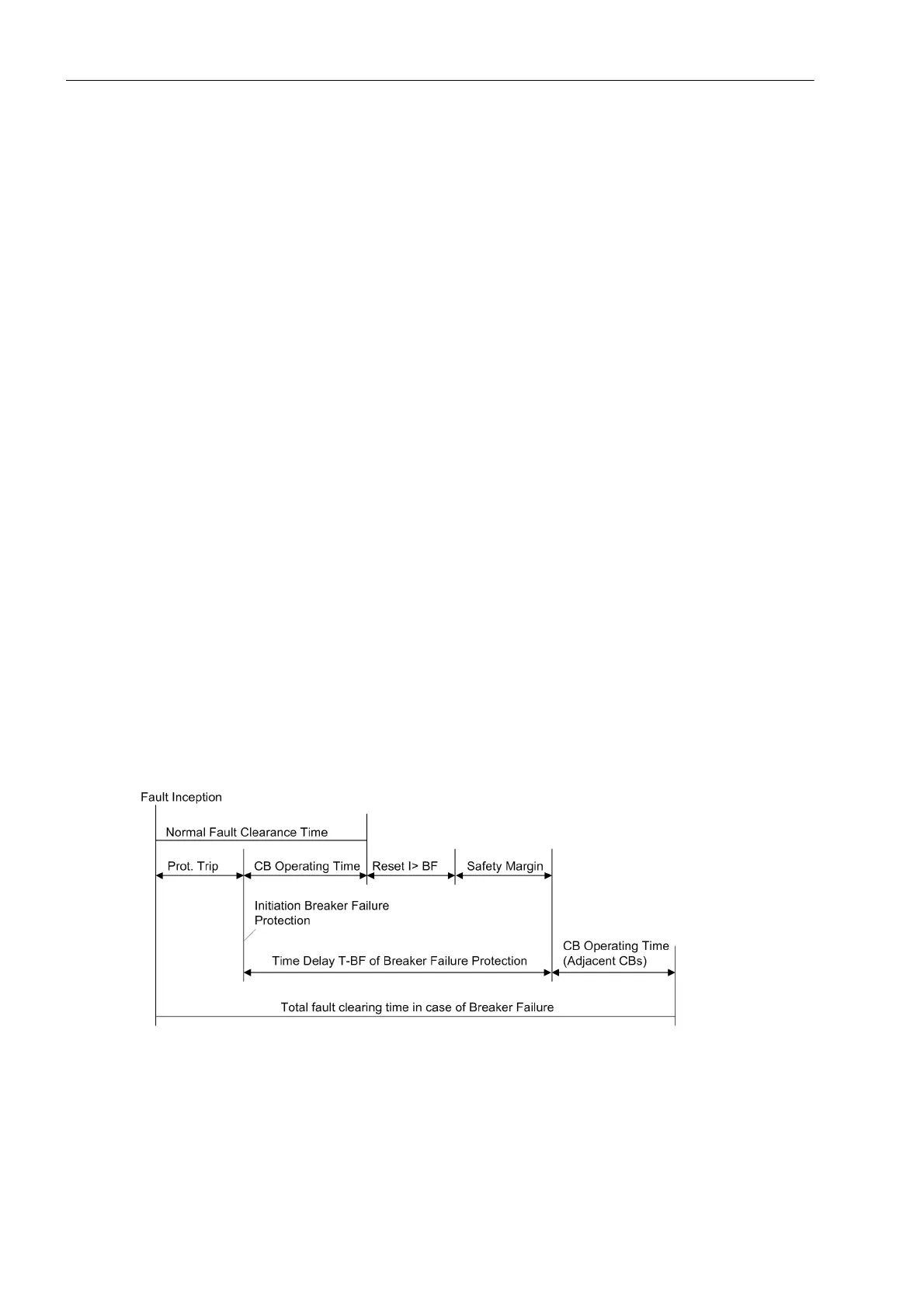
Time Delay
The time delay is entered at address 7004 TRIP-Timer and is based on the maximum breaker disconnecting
time, the dropout time of overcurrent detection plus a safety margin which takes into consideration delay time
runtime deviation. The time sequences are illustrated in the following figure.
Figure 2-122 Time Sequence for Typical Fault Clearance and for Breaker Failure

 Loading...


