Appendix
A.4 Default Settings
SIPROTEC, 7UM62, Manual
C53000-G1176-C149-7, Release date 03.2010
565
A.4 Default Settings
When the device leaves the factory, a large number of LED indicators, binary inputs and outputs as well as
function keys are already preset. They are summarized in the following table.
A.4.1 LEDs
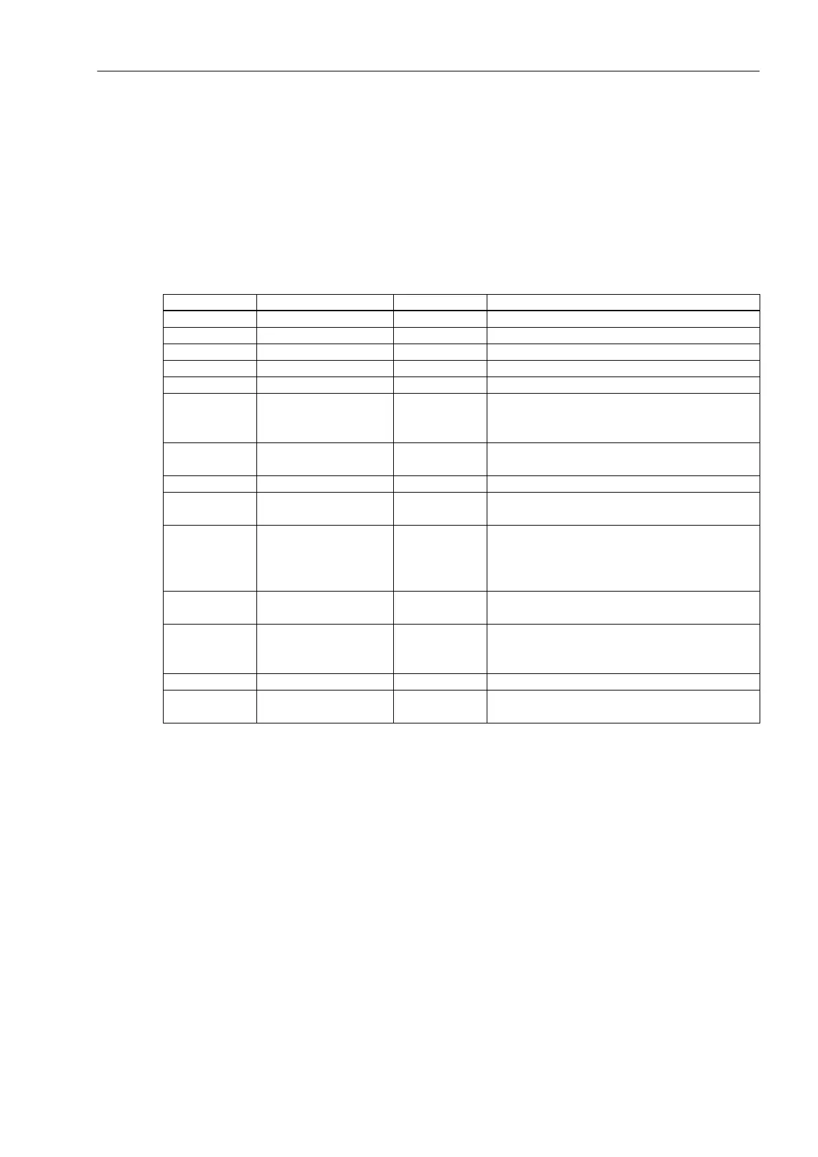
Table A-2 LED Indication Presettings
LEDs Allocated Function Function No. Description
LED1 Relay TRIP 511 Relay GENERAL TRIP command
LED2 Relay PICKUP 501 Relay PICKUP
LED3 I> Fault L1 1811 O/C fault detection stage I> phase L1
LED4 I> Fault L2 1812 O/C fault detection stage I> phase L2
LED5 I> Fault L3 1813 O/C fault detection stage I> phase L3
LED6 IEE> TRIP 1226 IEE> TRIP
U0> TRIP 5187 Stator earth fault: U0 stage TRIP
S/E/F TRIP 5193 Stator earth fault protection TRIP
LED7 Error PwrSupply 147 Error Power Supply
Fail Battery 177 Failure: Battery empty
LED8 Diff TRIP 5671 Differential protection TRIP
LED9 Pr TRIP 5097 Reverse power: TRIP
Pr+SV TRIP 5098 Reverse power: TRIP with stop valve
LED10 Exc<3 TRIP 5343 Underexc. prot. char. 3 TRIP
Exc<1 TRIP 5344 Underexc. prot. char. 1 TRIP
Exc<2 TRIP 5345 Underexc. prot. char. 2 TRIP
Exc<U<TRIP 5346 Underexc. prot. char.+Uexc< TRIP
LED11 I2>> TRIP 5160 Unbalanced load: TRIP of current stage
I2 Θ TRIP 5161 Unbalanced load: TRIP of thermal stage
LED12 f1 TRIP 5236 f1 TRIP
f2 TRIP 5237 f2 TRIP
f3 TRIP 5238 f3 TRIP
LED13 f4 TRIP 5239 f4 TRIP
LED14 U> TRIP 6570 Overvoltage U> TRIP
U>> TRIP 6573 Overvoltage U>> TRIP

 Loading...


