Functions
2.12 Unbalanced Load (Negative Sequence) Protection (ANSI 46)
SIPROTEC, 7UM62, Manual
C53000-G1176-C149-7, Release date 03.2010
94
2.12.2 Setting Notes
General
Unbalanced load protection is only in effect and accessible if address 117 UNBALANCE LOAD is set to
Enabled during configuration. If the function is not required, it is set to Disabled.
The address 1701 UNBALANCE LOAD serves to switch the unbalanced load protection ON or OFF or to block
only the trip command (Block relay).
The maximum permissible, permanent negative phase-sequence current is important for the thermal model.
For machines of up to 100 MVA with non-salient pole rotors, this typically amounts to at least 6 % to 8 % of the
nominal machine current, and with salient-pole rotors at least 12 %. For larger machines and in cases of doubt,
please refer to the instructions of the machine manufacturer.
It is important to note that the manufacturer's data relate to the primary values of the machine, for example, the
maximum permissible permanent inverse current referring to the nominal machine current is indicated. For set-
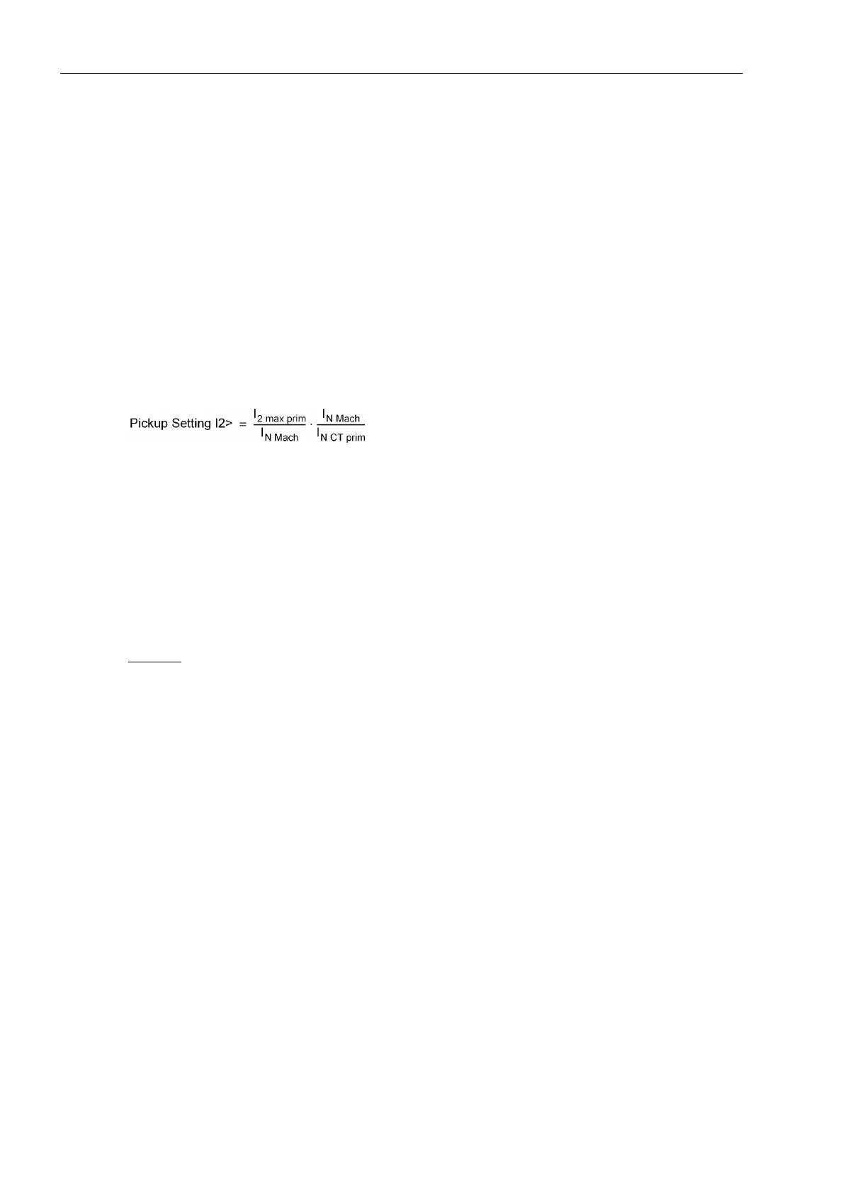
tings on the protective relay, this data is converted to the secondary inverse current. The following applies
with
I
2 max prim
Permissible long-term thermal inverse current of the machine
I
N Mach
Nominal current of the machine
I
N CT prim
Primary nominal current of the current transformer
Pickup Threshold / Warning Stage
The value for I2> is set at address 1702. It is at the same time the pickup value for a current warning stage
whose delay time T WARN is set at address 1703.
Example:
Asymmetry factor K
If the machine manufacturer has indicated the loadability duration due to an unbalanced load by means of the
constant K = (I
2
/I
N
)
2
·t, it is set immediately at the address 1704 FACTOR K. The constant K is proportional to
the admissible energy loss.
Machine I
N Mach
= 483 A
I
2 max prim
/ I
N Mach
= 11 % permanent (salient-pole machine, see
Figure 2-25)
Current transformer I
N CT prim
= 500 A
Setting value I
2 perm.
= 11 % · (483 A/500 A) = 10.6 %

 Loading...


