Technical Data
4.1 General
SIPROTEC, 7UM62, Manual
C53000-G1176-C149-7, Release date 03.2010
454
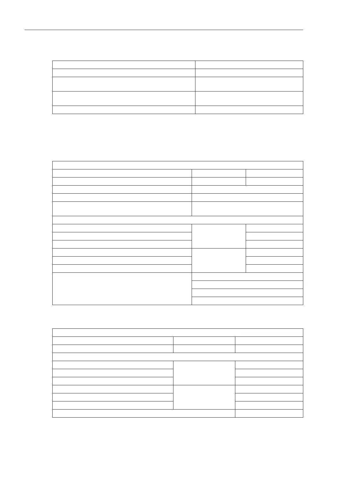
Analog output (for operational measured values)
4.1.2 Auxiliary Voltage
DC Voltage
AC Voltage
Nominal Range 0 mA to 20 mA or 4 mA to 20 mA
Operating Range 0 mA to 22.5 mA or 4 mA to 22.5 mA
Connection for flush-mounted case Rear panel, mounting location "B" or/and "D"
9-pin DSUB female connector
For Panel Surface-Mounted Case At the terminal on the case bottom or/and at
the housing top
Max. Burden 350 Ω
Voltage Supply via Integrated Converter
Nominal auxiliary voltage DC U
Aux
DC 24 V/48 V DC 60 V/110 V/125 V
Admissible voltage ranges DC 19 V to 58 V DC 48 V to 150 V
Nominal auxiliary voltage DC U
Aux
DC 110 V/125 V/220 V/250 V
Permissible voltage ranges DC 88 V to 300 V
Admissible AC ripple voltage,
Peak to Peak, IEC 60255-11
≤15 % of the Auxiliary Voltage
Power input
7UM621 Quiescent approx. 5.5 W
7UM622 approx. 5.7 W
7UM623 approx. 8.1 W
7UM621 Energized approx. 12.5 W
7UM622 approx. 14.6 W
7UM623 approx. 14.6 W
Bridging time in the event of power failure/short circuit ≥ 50 ms at U ≥ DC 48 V (U
Aux,N
= 24 V/48 V)
≥ 50 ms at U ≥ DC 110 V (U
Aux,N
= 60 V to 125 V)
≥ 20 ms at U ≥ DC 24 V (U
Aux,N
= 24 V/48 V)
≥ 20 ms at U ≥ DC 60 V (U
Aux,N
= 60 V to 125 V)
Voltage supply via integrated converter
Nominal auxiliary voltage AC U
Aux
AC 115 V (50 Hz or 60 Hz) AC 230 V (50 Hz or 60 Hz)
Admissible voltage ranges AC 92 V to 132 V AC 184 V to 265 V
Power input
7UM621 Quiescent approx. 5.5 VA
7UM622 approx. 5.5 VA
7UM623 approx. 5.5 VA
7UM621 Energized approx. 13 VA
7UM622 approx. 15 VA
7UM623 approx. 13 VA
Bridging time in the event of power failure/short circuit ≥ 200 ms

 Loading...


