Functions
2.17 Reverse Power Protection (ANSI 32R)
SIPROTEC, 7UM62, Manual
C53000-G1176-C149-7, Release date 03.2010
146
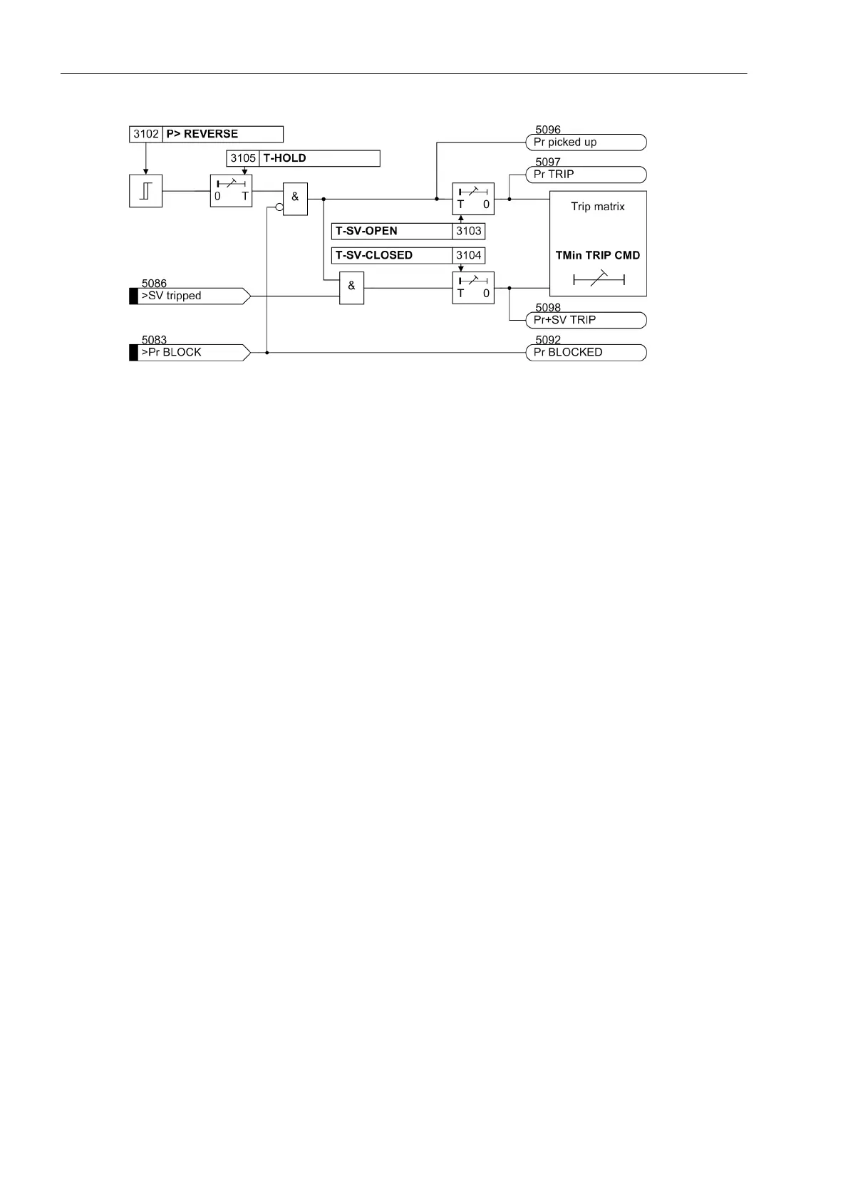
Figure 2-59 Logic Diagram of the Reverse Power Protection
2.17.2 Setting Notes
General
Reverse power protection is only effective and available if this function was set during protective function con-
figuration (Section 2.4), address 131, REVERSE POWER is set to Enabled. If the function is not required
Disabled is set. The address 3101 REVERSE POWER serves to switch the function ON or OFF or to block only
the trip command (Block relay).
In case of a reverse power, the turbine set must be disconnected from the system as the turbine operation is
not permissible without a certain minimum steam throughput (cooling effect) or, in case of a gas turbine set, the
motor load would be too heavy for the network.
Pickup Values
The level of the active power input is determined by the friction losses to be overcome and is in the following
ranges, depending on the individual system:
• Steam turbines: P
Reverse
/S
N
≈ 1 % to 3 %
• Gas turbines: P
Reverse
/S
N
≈ 3 % to 5 %
• Diesel drives: P
Reverse
/S
N
> 5 %
For the primary test, the reverse power should be measured with the actual protection. The user should select
a setting of 0.5 times the value of the measured motoring energy. This value can be found under the percentage
operational measured values. The feature to correct angle faults of the current and voltage transformers should
be used especially for very large machines with a particularly low motoring energy (see Sections 2.5 and 3.3).

 Loading...


