Functions
2.30 100-%-Stator Earth Fault Protection with 3rd Harmonics (ANSI 27/59TN 3rd Harm.)
SIPROTEC, 7UM62, Manual
C53000-G1176-C149-7, Release date 03.2010
215
2.30 100-%-Stator Earth Fault Protection with 3rd Harmonics
(ANSI 27/59TN 3rd Harm.)
The measurement method described in section 2.28 is based on the fundamental wave of the displacement
voltage and allows protecting up to 90 % to 95 % of the stator winding. A non-line-frequency voltage must be
used to achieve 100 % protection. In the 7UM62, the 3rd harmonic is used for this purpose.
2.30.1 Functional Description
Mode of Operation
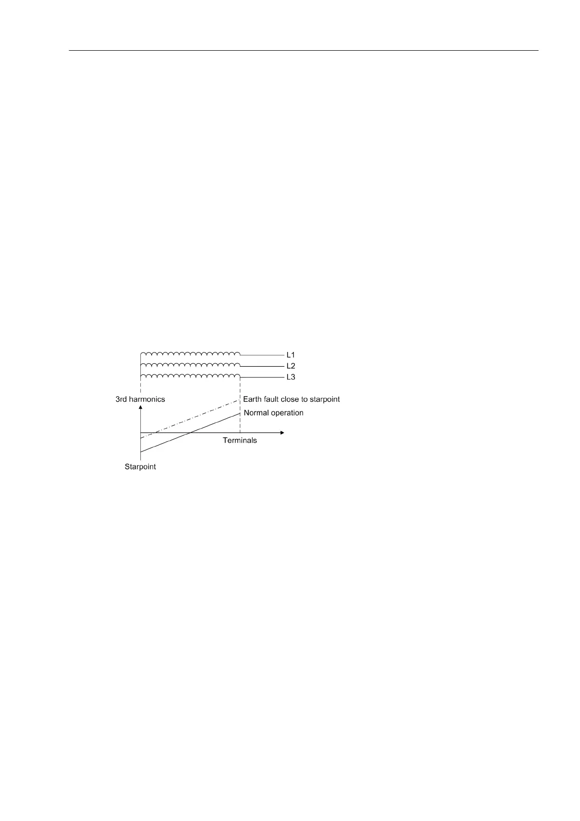
The 3rd harmonic emerges in each machine in a more or less significant way. It is caused by the shape of the
poles. If an earth fault occurs in the generator stator winding, the division ratio of the parasitic capacitances
changes, since one of the capacitances is short-circuited by the earth fault. During this procedure, the 3rd har-
monic measured in the starpoint decreases, whereas the 3rd harmonic measured at the generator terminals
increases (see the following figure). The 3rd harmonic forms a zero phase-sequence system and can thus also
be determined by means of the voltage transformer switched in wye/delta or by calculating the zero phase-se-
quence system from the phase-earth-voltages.
Figure 2-92 Profile of the 3rd Harmonic along the Stator Winding
Moreover, the extent of the 3rd harmonic depends on the operating point of the generator, i.e. a function of
active power P and reactive power Q. For this reason, the working range of the stator earth fault protection is
restricted in order to increase security.
With busbar connection all machines contribute to the 3rd harmonic, which impedes separation of the individual
machines.

 Loading...


