Functions
2.42 Monitoring Functions
SIPROTEC, 7UM62, Manual
C53000-G1176-C149-7, Release date 03.2010
285
2.42.1.3 Monitoring of External Transformer Circuits
Interruptions or short circuits in the secondary circuits of the current and voltage transformers, as well as faults
in the connections (important for commissioning!), are detected and reported by the device. The measured
values are cyclically checked in background routines for this purpose, as long as no system fault is present.
Current Symmetry
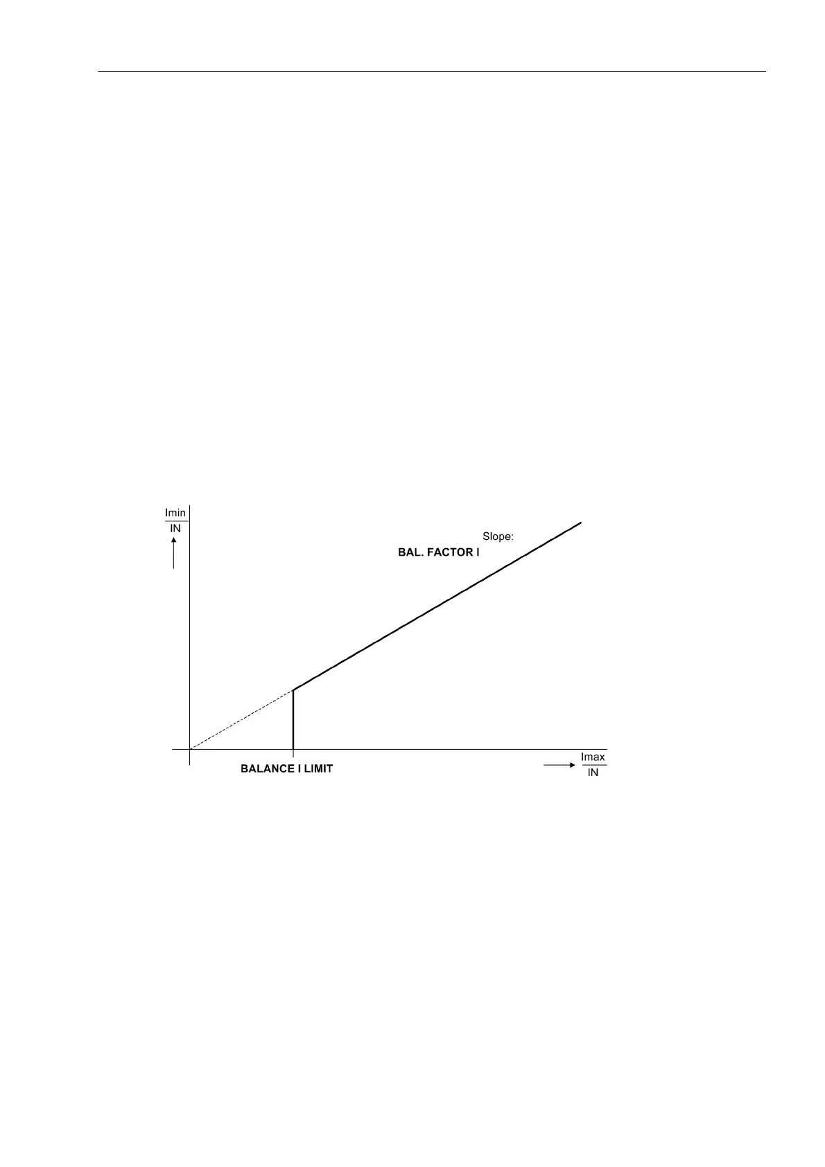
The currents fed in at the current inputs of side 1 and side 2 are monitored for symmetry. During normal system
operation a certain degree of symmetry of the currents is expected. This symmetry is checked by the device,
using an amplitude monitor. The smallest phase current is compared to the largest phase current. Asymmetry
is recognized if:
| I
min
| / | I
max
| < BAL. FACT. I S1 as long as I
max
/ I
N
> BAL. I LIMIT S1 / I
N
| I
min
| / | I
max
| < BAL. FACT. I S2 as long as I
max
/ I
N
> BAL. I LIMIT S2 / I
N
where I
max
is the largest of the three phase currents and I
min
is the smallest. The symmetry factor BAL. FACT.
I S1 or BAL. FACT. I S2 represents the admissible asymmetry of the phase currents whereas the limit
value BAL. I LIMIT S1 or BAL. I LIMIT S2 is the lower limit of the operating range of this monitoring
(see following figure). The dropout ratio is about 95 %.
This fault is signaled with „Fail. Isym 1“ or „Fail. Isym 2“ separately for side 1 and side 2.
Figure 2-133 Current symmetry monitoring
Voltage Symmetry
During normal system operation a certain degree of symmetry among the voltages is expected. With two
phase-phase voltages and the displacement voltage U
E
connected to the device, the third phase-phase voltage
is calculated. The rectified mean values are formed from the phase-earth voltages, and checked for the sym-
metry of their amounts. The smallest phase voltage is compared to the largest. Asymmetry is recognized if:
| U
min
| / | U
max
| < BAL. FACTOR U as long as | U
max
| > BALANCE U-LIMIT
where U
max
is the highest of the three voltages and U
min
the smallest. The symmetry factor BAL. FACTOR U
is the measure for the asymmetry of the conductor voltages; the limit BALANCE U-LIMIT is the lower limit of
the operating range of this monitoring (see following figure). Both parameters can be set. The dropout ratio is
about 95 %.

 Loading...


