Functions
2.41 Analog Outputs
SIPROTEC, 7UM62, Manual
C53000-G1176-C149-7, Release date 03.2010
277
2.41.2 Setting Notes
General
You have specified during configuration of the analog outputs (Section 2.4.2, addresses173 to 176) for analog
output type 1 and addresses 200 to 203 for analog output type 2 which of the analog inputs in the device will
be used for which measured value. Please remember that you can assign only one output type to an analog
channel. If a function is not needed, Disabled is set. The other parameters associated with this analog output
are hidden in that case.
Measured Values for Analog Outputs of Type 1
Once the measured values are selected for the analog outputs (Section 2.4.2, Addresses 173 to 176), set the
conversion factor and the valid range for the available outputs, as follows:
• For analog output B1 at location "B" (port B1):
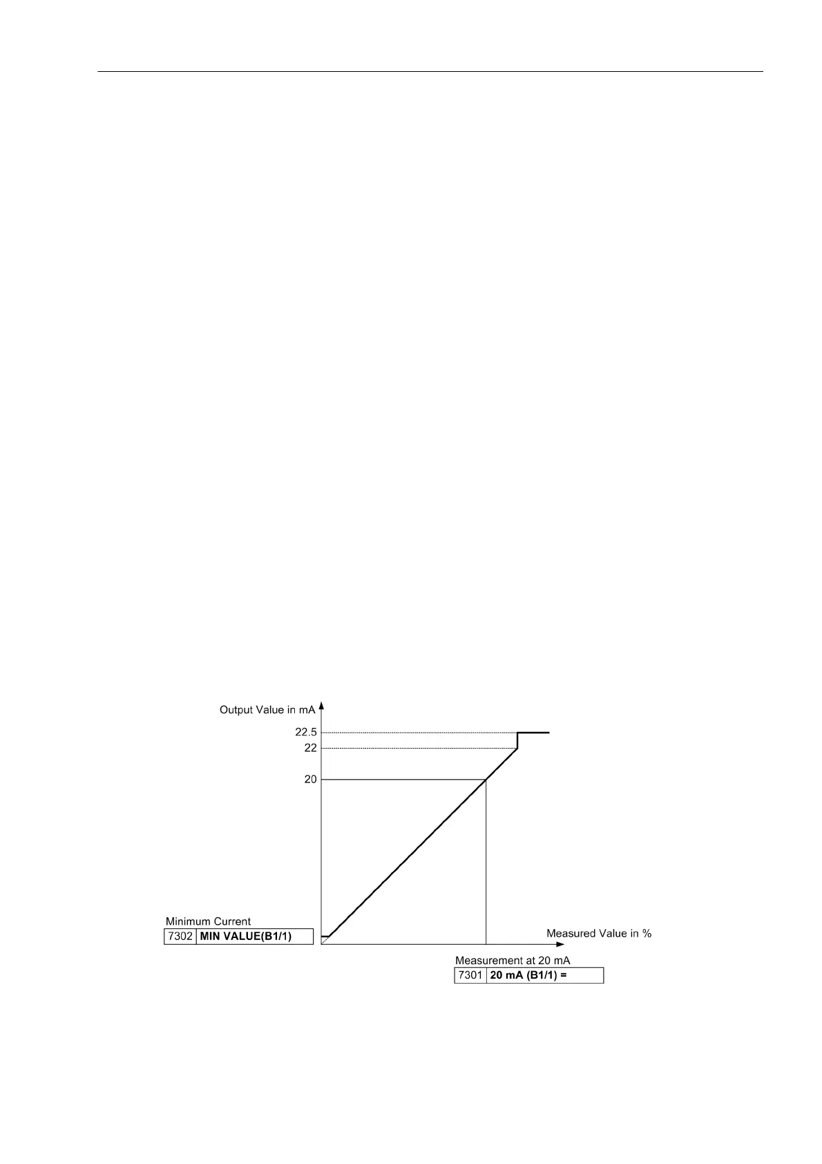
At address 7301 20 mA (B1/1) = the percent value to be displayed at 20 mA.
Address 7302 MIN VALUE(B1/1) the smallest valid value.
• For analog output B2 at location "B" (port B2):
At address 7303 20 mA (B2/1) = the percent value to be displayed at 20 mA.
Address 7304 MIN VALUE(B2/1) the smallest valid value.
• For analog output D1 at location "D" (port D1):
At address 7305 20 mA (D1/1) = the percent value to be displayed at 20 mA.
Address 7306 MIN VALUE(D1/1) the smallest valid value.
• For analog output D2 at location "D" (port D2):
At address 7307 20 mA (D2/1) = the percent value to be displayed at 20 mA.
Address 7308 MIN VALUE(D2/1) the smallest valid value.
The maximum possible value is 22.0 mA; in case of an overflow (value outside the maximum permissible
range) 22.5 mA is output.
The following diagram illustrates the relationships.
Figure 2-128 Definition of output range display for type 1

 Loading...


