Functions
2.29 Sensitive Earth Fault Protection (ANSI 51GN, 64R)
SIPROTEC, 7UM62, Manual
C53000-G1176-C149-7, Release date 03.2010
213
2.29.2 Setting Notes
General
The sensitive earth fault protection is only effective and available if address 151 O/C PROT. IEE> = with
IEE1 or with IEE2 is assigned. If when configuring the 90 % stator earth fault protection (150 S/E/F PROT.,
see subsection 2.4) one of the options with current value is chosen, the sensitive current measuring inpu of
the device 7UM62 is thus occupied. The user must be aware that the sensitive earth fault detection may use
the same measuring input (I
EE2
) and thus the same measuring quantity. If sensitive earth fault detection is not
required, Disabled is set. Address 5101 O/C PROT. IEE serves to switch the function ON or OFF or to
block only the trip command (Block relay).
Use as Rotor Earth Fault Protection
The sensitive earth current protection can be used to detect earth faults either in the stator or in the rotor
winding of the generato, provided that the magnitude of the earth current alone is sufficient as a criterion. In
very high-ohmic circuits or those isolated from earth, sufficiently large earth currents must be ensured.
When, for example, used as rotor earth fault protection, a system frequency bias voltage (U
V
≈ 42 V) must be
applied to the rotor circuit by means of the 7XR61series device in Figure „ The application case as rotor earth
fault protection“ in Section 2.29). Because of this bias voltage, a current flows through the earth capacitance
even with proper earth isolation, which can be used as a criterion for a closed measuring circuit (address 5106
IEE<). Approximately 2mA is a typical pickup value. The monitoring stage is ineffective is this value is set to 0.
This can become necessary if the earth capacitances are too small.
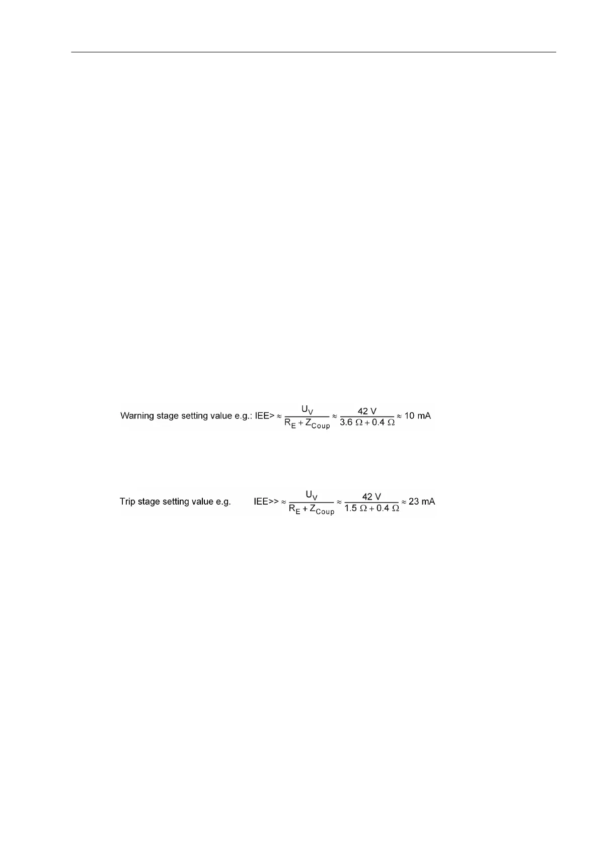
The earth current pick-up value 5102 IEE> is chosen such that isolation resistances R
E
between 3 kΩ to 5
kΩ can be detected:
Where the setting value should be at least twice the interference current caused by the earth capacitances of
the rotor circuit.
The 5104 IEE>> trip stage should be dimensioned for a fault resistance of about 1.5 kΩ.
with Z
Coup
= Impedance of the series device at nominal frequency.
The 5103 T IEE> and 5105 T IEE>> tripping time delay do not include the operating times.
Use as Stator Earth Fault Protection
Please see also Section 2.28. For use as stator earth fault protection, the earth current may have to be in-
creased by an ohmic load resistor at the earthing transformer. Instructions for dimensioning the earth current
transformer and loading resistor are given in the publication "Planning Machine Protection Systems" /5/.
Use as Earth Fault Protection
For low-voltage machines with incorporated neutral conductor or machines with low-impedance earthed star-
point, the time-overcurrent protection of the phase branches already is an earth short-circuit protection, since
the earth fault current also flows through the faulty phase . If the sensitive earth current detection nevertheless
shall be used as short-circuit to earth protection, an external intermediate transformer must be used to ensure
that the short-circuit current does not exceed the thermal limit values (15 A continuous, 100 A for < 10 s, 300
A for < 1 s) of this measuring input..

 Loading...


