Mounting and Commissioning
3.3 Commissioning
SIPROTEC, 7UM62, Manual
C53000-G1176-C149-7, Release date 03.2010
411
Finally switch the AC voltage source of the 7XT71 off. After about 5 s the protection device issues the indication
„Fail REF 1-3Hz“ (not allocated on delivery).
To eliminate interference which might originate from the running machine, in particular from the excitation
system, it is recommended to perform an additional operational check.
3.3.8 Checking the 100 % Stator Earth Fault Protection
100 % Stator Earth Fault Protection
The 100-% stator earth fault protection can be checked with the machine at standstill, because the measuring
principle for the earth resistance calculation is independent of whether the machine is at standstill, rotating or
excited. A prerequisite is, however, that the 20 Hz generator 7XT33 must be supplied with a DC voltage or an
external voltage source (3 x 100 V, 50/60 Hz), depending on the project, (see also the connection examples in
Section 2.31).
Switch the 100-% stator earth fault protection (address 5301 100% SEF-PROT.) to Block relay).
The following parameter default settings must be maintained for a first commissioning.
5309 PHI I SEF = 0 °
5310 SEF Rps = 0.0 Ω
5311 Rl-PARALLEL = ∞ Ω
The measured quantities U
SEF
and I
SEF
fed to the device can now be read out in the earth fault measured values
(in DIGSI under Earth fault measured values):
„U SEF=“ xx.x V
„U20=“ xx.x V
„I SEF=“ xx.x mA
„I20=“ xx.x mA
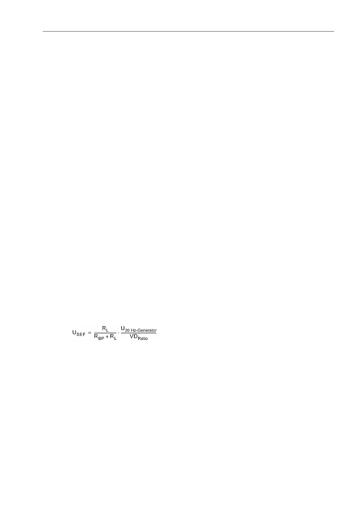
Please note that these measurements U SEF and I SEF are pure rms values which only correspond to the 20
Hz quantities (U20 and I20) if the generator is at standstill. The voltage measured is influenced by the loading
resistor R
L
, the 20 Hz resistance of the bandpass (R
BP
approx. 8 Ω), the voltage divider (ü
Vlt.Divider
, usually 5/2)
and, in the final analysis, by the 20 Hz supply voltage (U
20Hz-Generator
, approx. 25 V). The value can be estimated
as follows:
The flowing current I
SEF
is determined by the stator earth capacitance and is very small.
From these values, the device calculates the earth resistance R
SEF
referred to the protection device side. The
primary earth resistance R
SEFp
on the machine side is obtained by multiplying the secondary value with the con-
version factor set in the Power System Data 1 (address 275 FACTOR R SEF). Both resistance values, including
the phase angle between the 20 Hz voltage and the 20 Hz current (ϕ
SEF
= ϕ
U
- ϕ
I
) can be read out in the oper-
ational measured values:
„R SEF=“ xxxx Ω
„RSEFp=“ xxx.xx kΩ
PHI I SEF xx.x°

 Loading...


