Mounting and Commissioning
3.1 Mounting and Connections
SIPROTEC, 7UM62, Manual
C53000-G1176-C149-7, Release date 03.2010
389
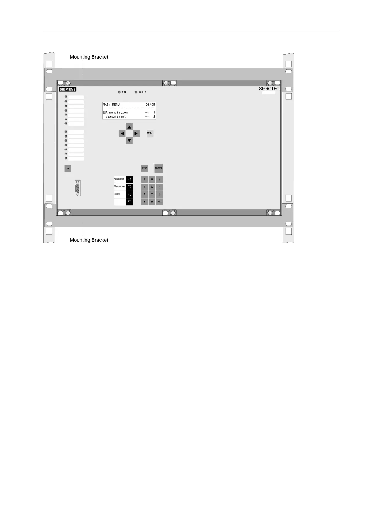
Figure 3-16 Rack or cubicle mounting of a device (housing size
1
/
1
)
3.1.3.3 Panel Surface Mounting
For panel surface mounting of the device proceed as follows:
• Secure the device to the panel with four screws. For dimensions refer to Section 4.39.
• Connect the low-resistance operational and protective earth to the ground terminal of the device. The cross-
sectional area of the ground wire must be equal to the cross-sectional area of any other control conductor
connected to the device. It must thus be at least 2.5 mm
2
.
• Alternatively, there is the possibility to connect the aforementioned earthing to the lateral grounding surface
with at least one M4 screw.
• Make the connections according to the circuit diagram via the screw-type terminals. Fibre-optic cables and
electrical communication modules are connected at the inclined housings. The SIPROTEC 4 System De-
scription /1/ has pertinent information regarding wire size, lugs, bending radii, etc.

 Loading...


