Functions
2.43 Trip Circuit Supervision
SIPROTEC, 7UM62, Manual
C53000-G1176-C149-7, Release date 03.2010
299
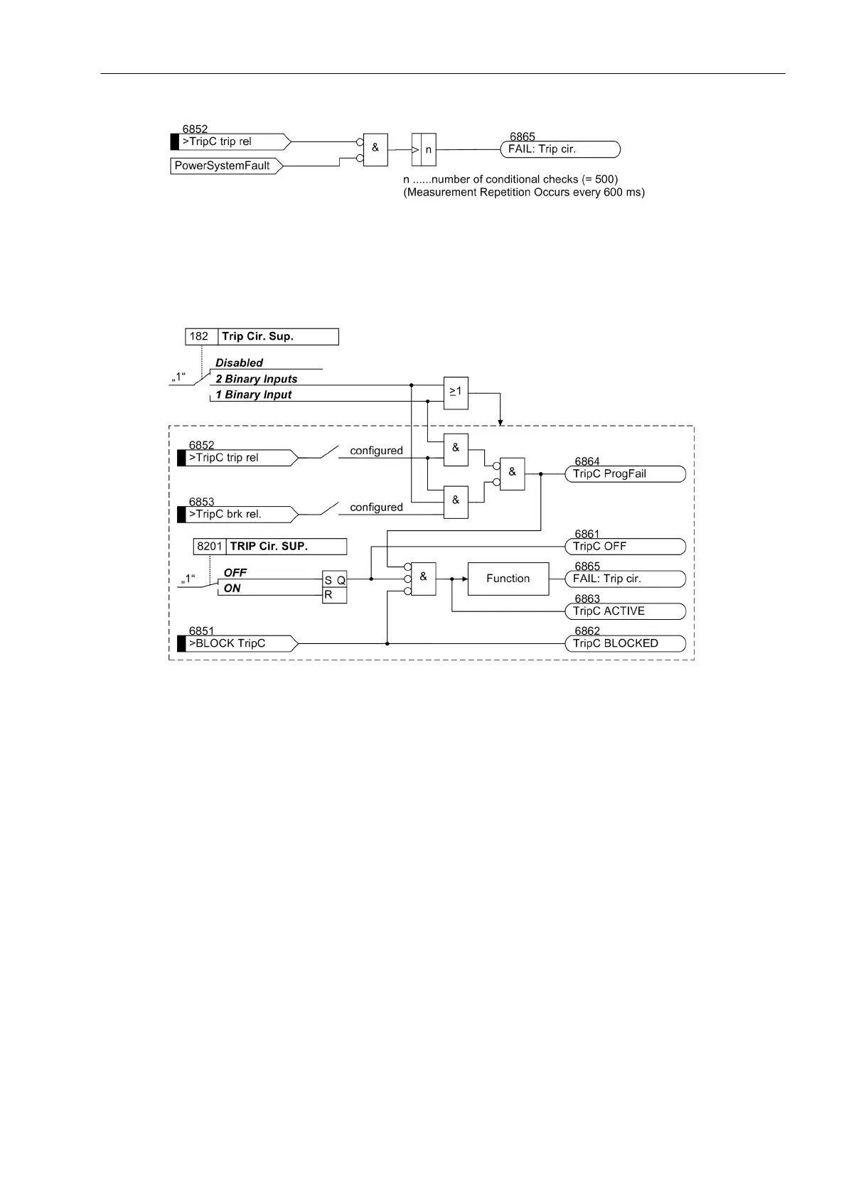
Figure 2-140 Logic diagram for Trip Circuit Monitoring with one binary input
The following figure shows the logic diagram for the message that can be generated by the trip circuit monitor,
depending on the control settings and binary inputs.
Figure 2-141 Message Logic of the Trip Circuit Supervision
2.43.2 Setting Notes
General
The function is only in effective and available if address 182 Trip Cir. Sup. (Section 2.4) was configured
to either 2 Binary Inputs or to 1 Binary Input as enabled, and the appropriate number of binary inputs
have been allocated for this purpose. The function at address 8201 TRIP Cir. SUP. must be set to ON. If
the allocation of the necessary binary inputs does not comply with the selected supervision mode, an alarm is
given („TripC ProgFail“). If the trip circuit monitor is not to be used at all, then at address 182 Disabled
is set. Further parameters are not needed. The indication of a trip circuit interruption is delayed by a fixed
amount of time. For two binary inputs, the delay is about 2 seconds, and for one binary input, the delay is about
300 s. This ensures that the longest possible duration of a trip signal expires, and an indication occurs only if
there is a real malfunction in the trip circuit.

 Loading...


