Functions
2.14 Differential Protection and Its Protected Objects
SIPROTEC, 7UM62, Manual
C53000-G1176-C149-7, Release date 03.2010
122
2.14.3.2 Setting Notes
Requirement
A precondition for the transformer differential protection function is that on configuration address 120 DIFF.
PROT. was set to 3 phase transf..
To ensure the correct polarity for the formation of the differential current, the polarity of the sets of CTs must be
specified. This was done during configuration by entering the location of the starpoints of the sets of CTs on
both sides of the transformer (addresses 201 STRPNT->OBJ S1 for side 1 and 210 STRPNT->OBJ S2 for
side 2, see Subsection P.System Data 1).
Also the nominal data (S
N TRANSF
, UU
N WIND S1
, U
N WIND S2
) of both sides of the transformer, as well as the primary
and secondary rated currents of the main CTs on both sides were queried. The settings are referred to these
values. They are also used e.g. for determining the primary measured values.
Information on starpoint handling on both sides is required for elimination of zero sequence current and for
measured value monitoring (summation current monitoring); it has already been entered during configuration
at addresses 242 STARPNT SIDE 1 and 244 STARPNT SIDE 2 (see Subsection 2.5.1).
Matching of Absolute Values and Vector Groups
When used as transformer protection, the 7UM62 automatically computes from the rated data of the protected
transformer the current-matching formulae which are required to match the vector group and the different rated
winding currents. The currents are converted such that the sensitivity of the protection always refers to the
rated apparent power of the transformer. No circuitry is required in general for vector group matching or for
manual conversions for rated currents.
The unit requires the following data for each winding
• Rated apparent power S
N
in MVA (see above),
• Rated voltage U
N
in kV (see above)
• Vector group numeral,
• Rated current of the current transformer set in A (see above).
Winding 1 is defined as the reference winding and therefore needs no numeral; the other windings are referred
to winding 1.
The reference winding is normally that of the higher voltage. If a reference winding other than the higher voltage
one is used, it must be noted that this changes the vector group numeral: E.g. a Dy5 transformer is regarded
from the Y side as Yd7.
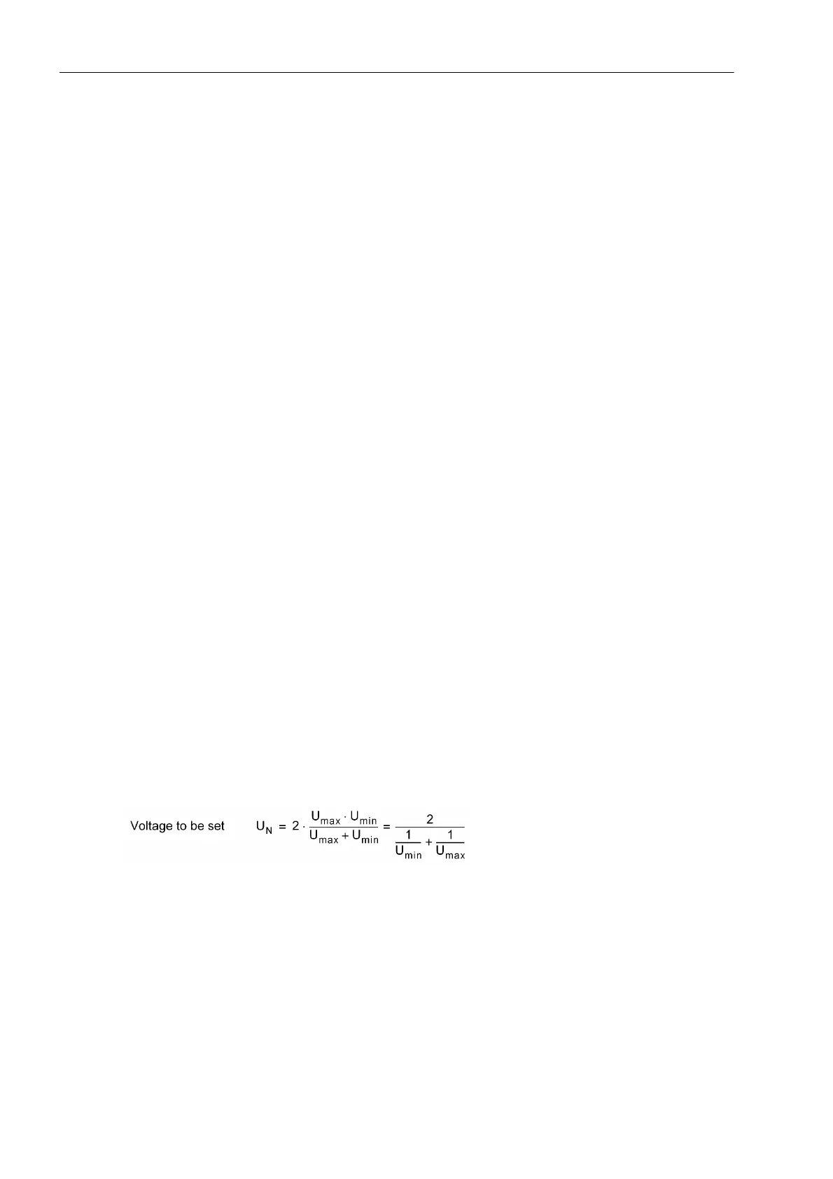
If a transformer winding is regulated, then the actual rated voltage of the winding is not used as U
N
, but rather
the voltage which corresponds to the average current of the regulated range.
If the setting of the protection should be performed with secondary values only (e.g. because external matching
transformers are present), the factory-set parameters of the transformer data can remain unchanged. With the
default setting of transformer data, the device effects a current matching of 1: 1 without phase displacement

 Loading...


