Functions
2.9 Definite-Time Overcurrent Protection (I>>, ANSI 50, 51, 67) with Direction Detection
SIPROTEC, 7UM62, Manual
C53000-G1176-C149-7, Release date 03.2010
69
2.9 Definite-Time Overcurrent Protection (I>>, ANSI 50, 51, 67) with
Direction Detection
The time-overcurrent protection is used as backup protection for the short-circuit protection of the protected
object. It also provides backup protection for downstream network components if faults there are not discon-
nected in time thus endangering the protected object.
The 7UM62 relay allows to choose between the input transformers of side 1 and side 2 for allocation of the
time-overcurrent protection function. This choice is made during configuration (see Section 2.4).
In order to ensure that pick-up always occurs even with internal faults, the protection - for generators - is usually
connected to the current transformer set in the neutral leads of the machine. If this is not the case for an indi-
vidual power system, the I>> stage can be combined with a short-circuit direction determination and switch off
a generator short circuit instantaneously ; the selectivity is not affected by this.
Initially, the currents are numerically filtered so that only the fundamental frequency currents are used for the
measurement. This makes the measurement insensitive to transient conditions at the inception of a short-
circuit and to asymmetrical short-circuit currents (d.c. component).
2.9.1 Functional Description
I>> Stage
Each phase-current of side 1 or 2 (depending on the configuration) is compared individually with the common
pickup value I>>, and indicated on overshoot. A trip signal is transmitted to the matrix as soon as the corre-
sponding T I>> time delays have expired. The dropout value is ± 95 % below the pick-up value.
Direction Detection
If this protection function has been assigned to the input transformers of side 1, the I>> stage is equipped with
a (disconnectable) direction element permitting a tripping only for faults in backward (i.e. machine) direction.
For this reason, this stage can be used particularly in applications where no current transformers exist in the
generator starpoint and undelayed tripping is nevertheless required on generator faults.
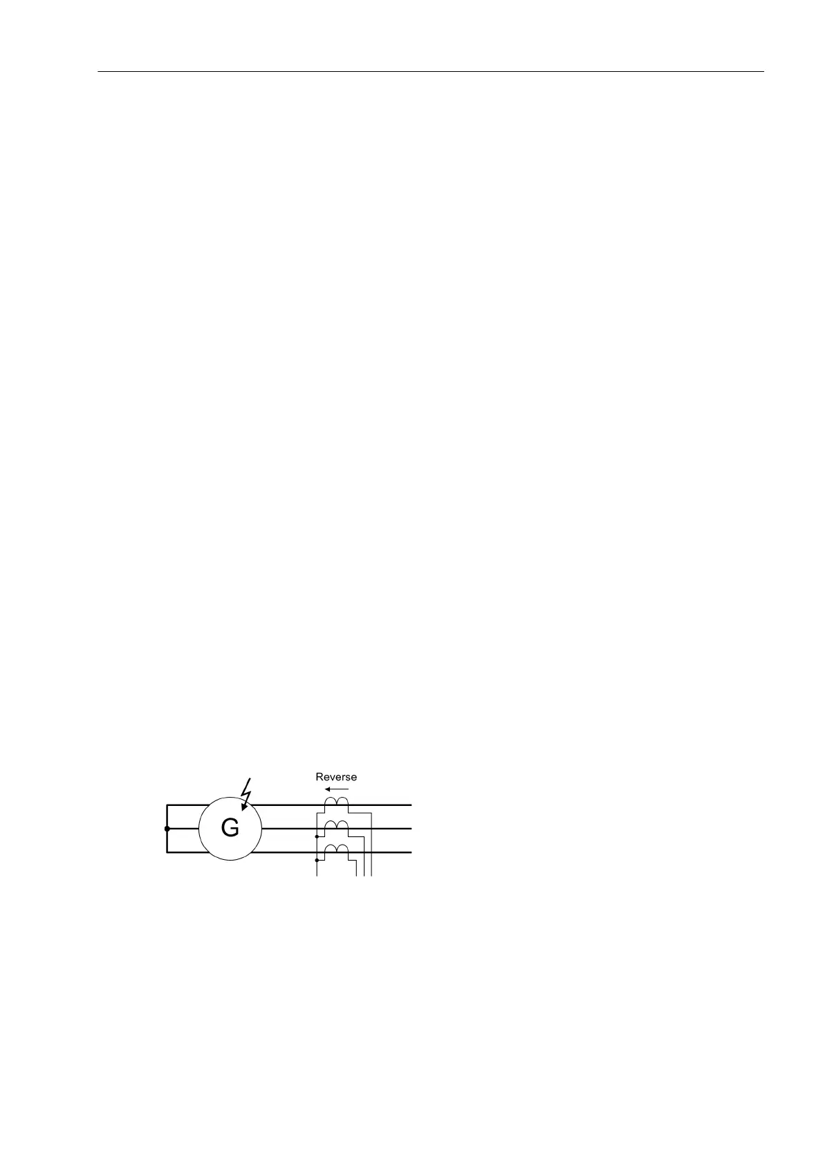
The definition of the current direction in Figure 2-13 applies for the CT of side 1. If the CT of side 2 is used,
Forward must be set to determine the current direction.
Figure 2-13 Selectivity via Short-Circuit Direction Detection
The direction is detected phase-selectively by means of a cross-polarized voltage. The phase-to-phase voltage
normally perpendicular to the fault current vector is used as unfaulted voltage (Figure 2-14). This is considered
during the calculation of the direction vector in the clockwise rotating phase sequence by a +90° rotation, and
in the anti-clockwise rotating phase by a -90° rotation. For phase-to-phase faults, the position of the direction
straight line may change in relation to the collapse of the short-circuit voltage.

 Loading...


