Functions
2.15 Earth Current Differential Protection (ANSI 87GN,TN)
SIPROTEC, 7UM62, Manual
C53000-G1176-C149-7, Release date 03.2010
133
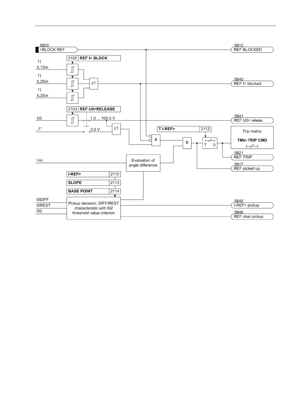
Figure 2-52 Logic Diagram of the Earth Current Differential Protection
with
1) Use of generator: I
LxSm
always side 1
Use of transformer: I
LxSm
according to allocation of sides
2.15.2 Setting Notes
General
A precondition for the operation of the earth current differential protection is that during the configuration of the
scope of functions (Section 2.4) the correct selection for the application in hand was made at address 121 REF
PROT.. If the protected object is a generator, the user can select either direct measurement of the starpoint
current via I
EE2
(Gen. with IEE2), or computed current (Gen. w. 3I0-S2). For the transformer the directly
measured zero sequence current is always used. It is however possible to select for the side allocation
(Transformer S1 or Transformer S2).
In power system data 1 the required settings must have been made. These are also necessary for normaliza-
tion and direction definition (see also Section 2.5 or 2.14.1). If the I
EE2
input is used, the protection device must
be notified of the neutral point transformer transformation ratio (prim./sec.) and the terminal of the earthing-side
CT to which the I
EE2
input is connected (see comments in Section 2.5).

 Loading...


