Functions
2.5 Power System Data 1
SIPROTEC, 7UM62, Manual
C53000-G1176-C149-7, Release date 03.2010
53
2.5 Power System Data 1
The device requires some plant and power system data to adapt its functions to the actual application. These
include, for instance, rated power system and transformer data, measured quantity polarities and connection,
breaker properties etc. There are also certain parameters common to all functions, i.e. not associated with a
specific protection, control or monitoring function. Section P.System Data 1 describes these data.
2.5.1 Setting Notes
General
The Power System Data 1 can be changed from the operator or service interface with a personal computer
using DIGSI.
In DIGSI double-click on Settings to display the relevant selection.
Connection of the Current Transformer Sets
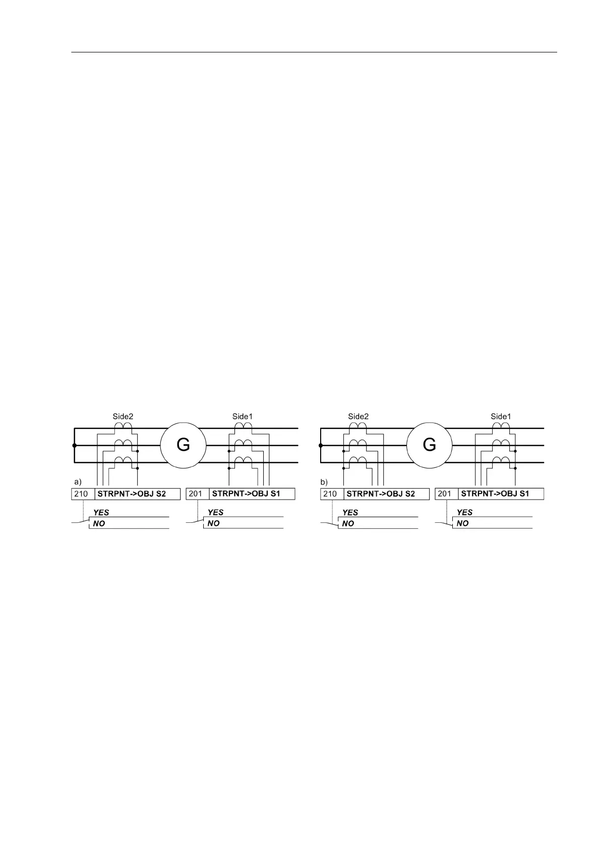
Under address 201 STRPNT->OBJ S1 the polarity of the current transformers of side 1 of the system needs
to be specified, i.e. according to the position of the wye-connected current transformer with reference to the
object to be protected. Address 210 STRPNT->OBJ S2 describes the polarity of the current transformers of
side 2. This setting determines the measuring direction of the device (STRPNT->OBJ S2 = YES = forward =
line direction). The following figure shows the definition even in cases where there are no starpoint CTs.
Figure 2-8 Location of starpoints for CTs of S1 and S2 - addresses 201 and 210 -
If the device is applied as transverse differential protection for generators or motors, special considerations
must be observed for the CT connections: In a healthy operational state all currents flow into the protected
object, i.e. in contrast to the other applications. Therefore you have to set a „wrong“ polarity for one of the
current transformer sets. The part windings of the machine windings correspond to the „sides“.
The following figure shows an example. Although the starpoints of both CT sets are turned towards the protect-
ed object, „side 2“ is set to the opposite: STRPNT->OBJ S2 = NO.

 Loading...


