Mounting and Commissioning
3.2 Checking Connections
SIPROTEC, 7UM62, Manual
C53000-G1176-C149-7, Release date 03.2010
392
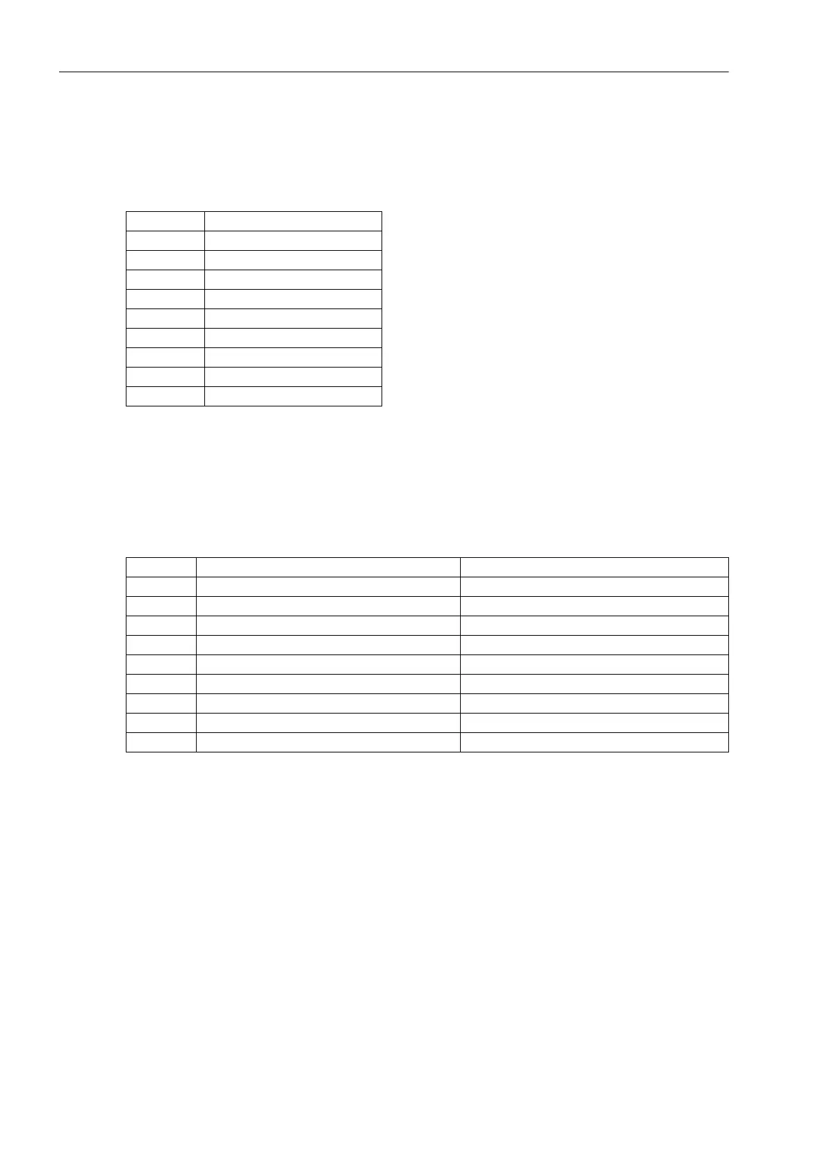
3.2.4 Analog Output
The two analog values are output as currents on a 9-pin DSUB socket. The outputs are isolated.
Table 3-25 Pin assignment of DSUB socket for analog output
3.2.5 Time Synchronization Interface
Either 5 VDC, 12 VDC or 24 VDC time synchronization signals can be processed if the connections are made
as indicated in the table below.
Table 3-26 D-subminiature connector assignment of the time synchronization interface
1)
assigned, but not used
For the pin assignment of the time synchronization interface in panel surface-mounted devices, please refer to
the Appendix (Figures A-3 and A-4).
Pin No. Code
1 Channel 1 positive
2–
3–
4–
5 Channel 2 positive
6 Channel 1 negative
7–
8–
9 Channel 2 negative
Pin No. Designation Signal Meaning
1 P24_TSIG Input 24 V
2 P5_TSIG Input 5 V
3 M_TSIG Return Line
4 M_TSYNC
1)
Return Line
1)
5 Shield Shield Potential
6– –
7 P12_TSIG Input 12 V
8 P_TSYNC
1)
Input 24 V
1)
9 SHIELD Shield Potential

 Loading...


