Appendix
A.3 Connection Examples
SIPROTEC, 7UM62, Manual
C53000-G1176-C149-7, Release date 03.2010
562
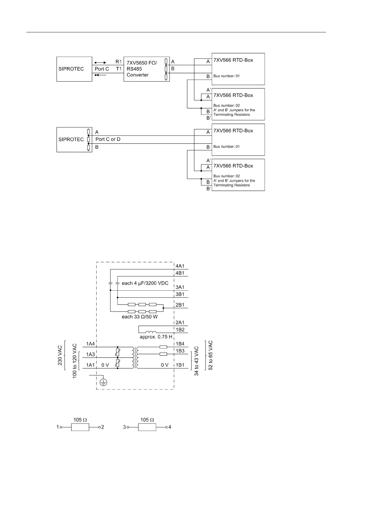
Figure A-21 Semiduplex Operation with two RTD Boxes
above: optical design (2 FOs)
below: design with RS485
A.3.3 Schematic Diagram of Accessories
Figure A-22 Schematic Diagram of Coupling Unit 7XR6100-0*A00 for Rotor Earth Fault Protection
Figure A-23 Schematic Diagram of Series Resistor 3PP1336-0DZ-K2Y

 Loading...


