Technical Data
4.3 Inverse-Time Overcurrent Protection (ANSI 51V)
SIPROTEC, 7UM62, Manual
C53000-G1176-C149-7, Release date 03.2010
466
4.3 Inverse-Time Overcurrent Protection (ANSI 51V)
Setting Ranges / Increments
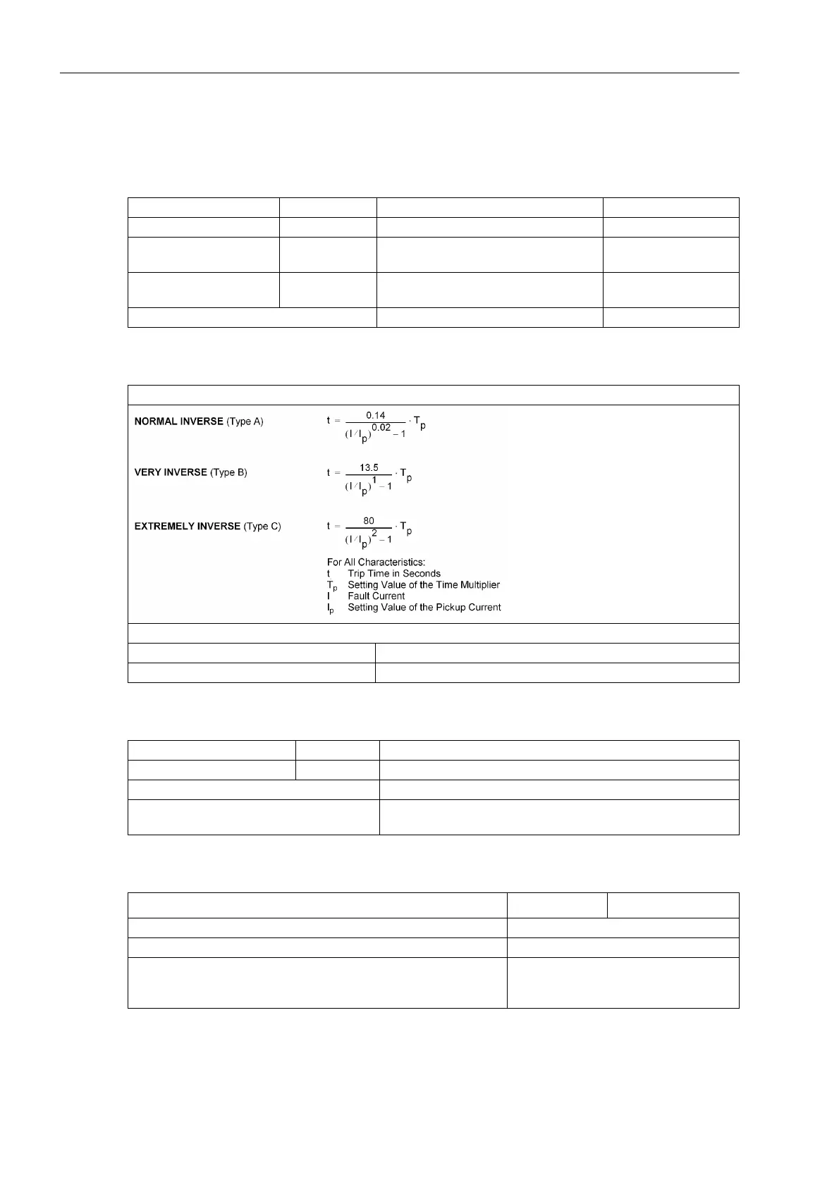
Trip Time Characteristics according to IEC
Tolerances
Influencing Variables for Pickup Values
Pickup current I
p
(phases) for I
N
= 1 A 0.10 A to 4.00 A Increments 0.01 A
for I
N
= 5 A 0.50 A to 20.00 A Increments 0.01 A
Time Multipliers T for I
p
IEC curves
0.05 s to 3.20 s
or ∞ (ineffective)
Increments 0.01 s
Time Multiplier D for I
p
ANSI curves
0.50 to 15.00
or ∞ (ineffective)
Increments 0.01
Undervoltage enable U< 10.0 V to 125.0 V Increments 0.1V
As per IEC 60255-3 (see also Figure 4-1)
The tripping times for I/I
p
≥ 20 are identical with those for I/I
p
= 20.
Pickup Threshold approx. 1.10 · I
p
Dropout Threshold approx. 1.05 · I
p
for I
p
/I
N
≥ 0.3,
Pickup currents I
p
for I
N
= 1 A 1 % of setting value or 10 mA
for I
N
= 5 A 1 % of setting value or 50 mA
Pickup of U< 1 % of setting value, or 0.5 V
Time for 2 ≤ I/I
p
≤ 20 5 % of reference (calculated) value +1 % current tolerance, or
40 ms
Power supply direct voltage in range 0.8 ≤ U
Aux
/U
AuxN
≤ 1.15 ≤ 1%
Temperature in range 23.00 °F (–5 °C) ≤ Θ
amb
≤ 131.00 °F (55 °C) ≤ 0.5 % / 10 K
Frequency in range 0.95 ≤ f/f
N
≤ 1.05 ≤ 1%
Harmonics
– Up to 10 % 3rd harmonic
– Up to 10 % 5th harmonic
≤ 1%
≤ 1%

 Loading...


