Functions
2.40 DC Voltage/Current Protection (ANSI 59NDC/51NDC)
SIPROTEC, 7UM62, Manual
C53000-G1176-C149-7, Release date 03.2010
271
2.40 DC Voltage/Current Protection (ANSI 59NDC/51NDC)
To detect DC voltages, DC currents and small AC quantities, the 7UM62 is equipped with a measuring trans-
ducer input (TD1) that can be used either for voltages (± 10V) or currents (± 20mA). Higher DC voltages are
connected via an external voltage divider. The DC voltage/DC current protection can be used, for example, for
the monitoring of the excitation voltage of synchronous machines or for the detection of earth faults in the DC
section of the start-up converter of a gas turbine set.
2.40.1 Functional Description
Principle of Function
A measuring transducer performs the analog/digital conversion of the measured quantity. The measuring trans-
ducer provides for galvanic isolation, a digital filter integrates the measurement voltage over two cycles and
suppresses high ripple content or non-periodic peaks in the measured value. A mean value of 32 samples is
generated. Since the absolute values are sampled, the result is always positive. Thus, the polarity of the voltage
is of no concern. When no suitable measured AC quantities are present ("operating condition 0"), the DC
voltage protection is still operative. The mean value is then calculated over 4 x 32 measured value samples.
If, in special cases, an AC voltage should be evaluated, select RMS as measurement method. The input quantity
is mathematically rectified, then the mean value calculated and reference to RMS made using factor 1.11.
Optionally, this function can be used for monitoring small currents, provided that the TD input has been config-
ured as current input and the settings of the associated jumpers on the C-I/O-6 have been changed. If the
jumper settings do not match the configuration parameters, an error message is output.
The protection can be set to operate for overvoltage or undervoltage. Pickup can be blocked via a binary input,
and the output signal can be time delayed.
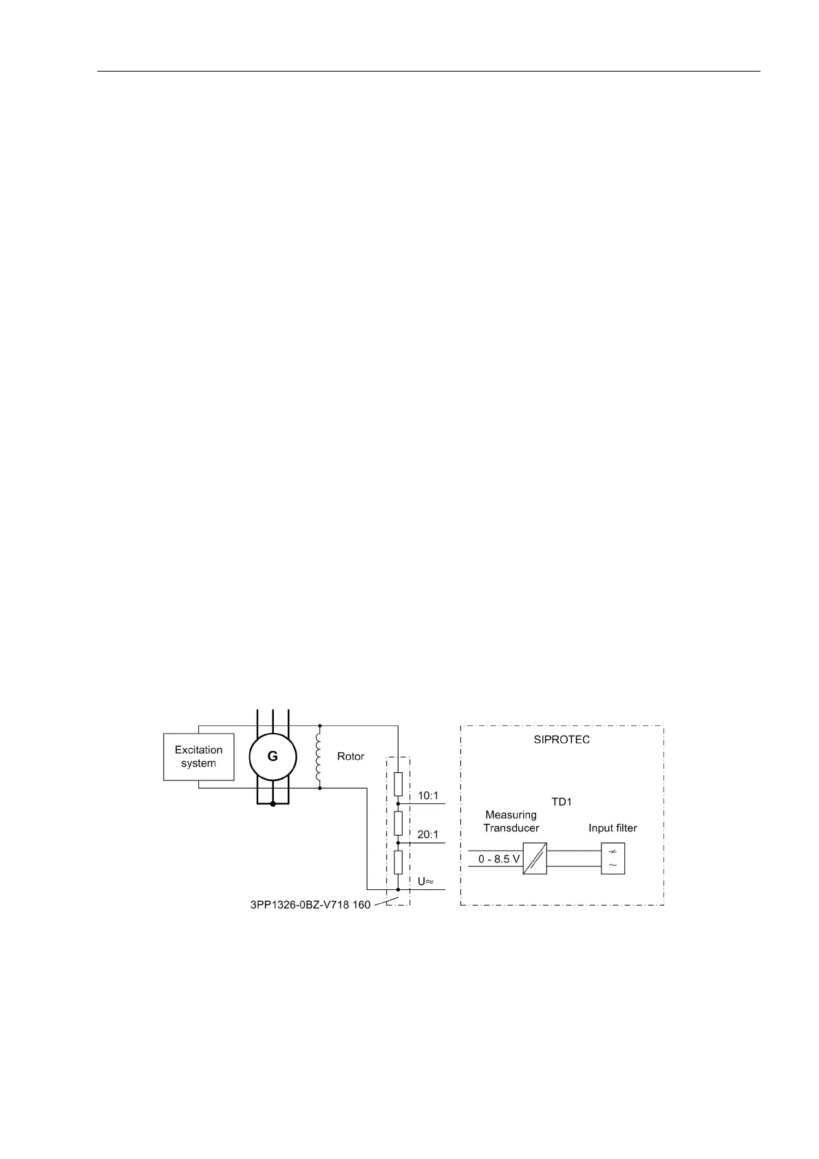
Excitation Voltage Monitoring
The following figure shows the excitation voltage monitoring. The excitation voltage is stepped down to a pro-
cessable level by a voltage divider, and fed to the measuring transducer.
Figure 2-125 DC Voltage Protection for Excitation Voltage Monitoring

 Loading...


