Functions
2.16 Underexcitation (Loss-of-Field) Protection (ANSI 40)
SIPROTEC, 7UM62, Manual
C53000-G1176-C149-7, Release date 03.2010
139
2.16.2 Setting Notes
General
The underexcitation protection is only effective and available if this function was set during protective function
configuration (Section 2.4), address 130, UNDEREXCIT. is set to Enabled. If the function is not required
Disabled is set. The address 3001 UNDEREXCIT. serves to enable the function ON and OFF or to block only
the trip command (Block relay).
The correct power system data input according to Section 2.5 is another prerequisite for the parameterization
of the underexcitation protection.
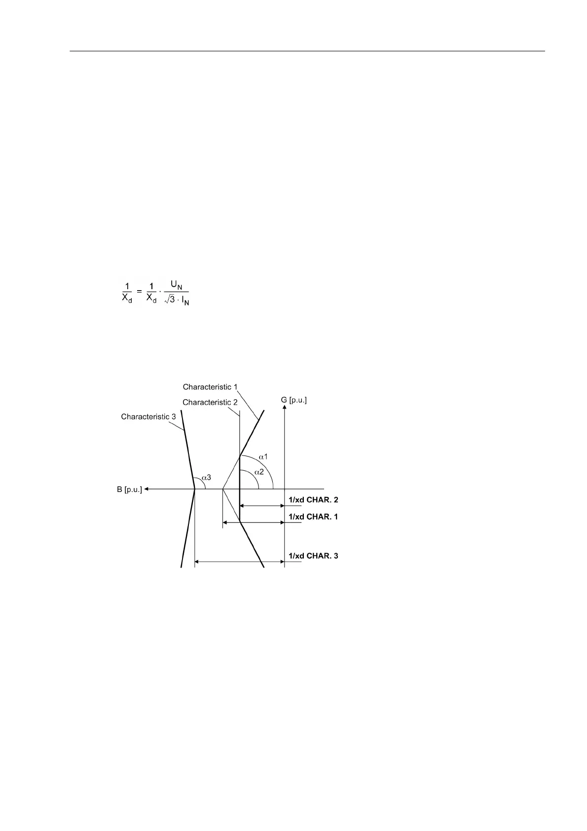
The trip characteristics of the underexcitation protection in the admittance value diagram are composed of
straight segments which are respectively defined by their admittance 1/xd (=coordinate distance) and their in-
clination angle α. The straight segments (1/xd CHAR.1)/α
1
(characteristic 1) and (1/xd CHAR.2)/α
2
(character-
istic 2) form the static underexcitation limit (see the following figure). (1/xd CHAR.1) corresponds to the recip-
rocal value of the related synchronous direct reactance.
If the voltage regulator of the synchronous machine has underexcitation limiting, the static characteristics are
set in such a way that the underexcitation limiting of the voltage regulator will intervene before characteristic 1
is reached (see figure 2-58).
Figure 2-56 Underexcitation Protection Characteristics in the Admittance Plane
Characteristic Curve Values
If the generator capability diagram (see the following figure) in its preferred representation (abscissa = positive
reactive power; ordinate = positive active power) is transformed to the admittance plane (division by U
2
), the
tripping characteristic can be matched directly to the stability characteristic of the machine. If the axis sizes are
divided by the nominal apparent power, the generator diagram is indicated per unit (the latter diagram corre-
sponds to a per unit representation of the admittance diagram).

 Loading...


