Functions
2.16 Underexcitation (Loss-of-Field) Protection (ANSI 40)
SIPROTEC, 7UM62, Manual
C53000-G1176-C149-7, Release date 03.2010
141
Instead of 1/x
d Mach
the approximate value I
K0
/I
N
can be used (with I
K0
= short-circuit current at no-load excita-
tion).
Setting example:
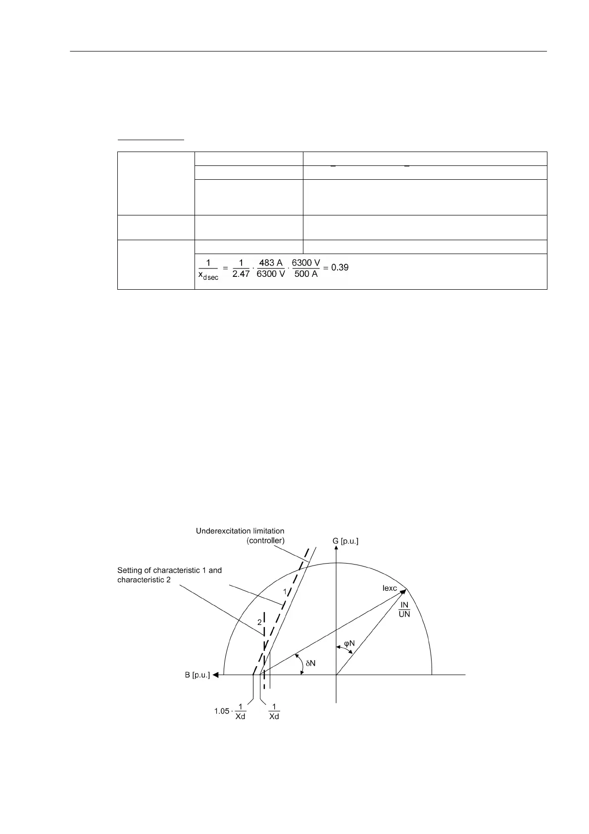
Multiplied by a safety factor of about 1.05, the setting value 1/xd CHAR. 1 results under address 3002.
For α1, the angle of the underexcitation limiting of the voltage regulator is selected or the inclination angle of
the machine stability characteristic is used. The setting value ANGLE 1 is typically situated between 60° and
80°.
In most cases, the machine manufacturer prescribes a minimum excitation value for small active powers. For
this purpose, characteristic 1 is cut from characteristic 2 for low active-power load. Consequently, 1/xd CHAR.
2 is set to about 0.9· (1/xd CHAR. 1), the ANGLE 2 to 90°. The kinked tripping limit according to Figure 2-56
(CHAR. 1, CHAR. 2) results in this way, if the corresponding time delays T CHAR. 1 and T CHAR. 2 of both
characteristics are set equally.
Characteristic 3 serves to adapt the protection to the dynamic machine stability limits. If there are no precise
indications, the user must select a value1/xd CHAR. 3 situated approximately between the synchronous
direct reactance x
d
and the transient reactance x
d
'. However, it should be greater than 1.
A value between 80° and 110° is usually selected for the corresponding ANGLE 3, which ensures that only a
dynamic instability can lead to a pickup with characteristic 3. The associated time delay is set at address 3010
T CHAR 3 to the value suggested in Table 2-8.
Figure 2-58 Admittance diagram of a turbogenerator
Machine U
N Mach
= 6.3 kV
I
N Mach
= S
N
/√3 U
N
= 5270 kVA/√3 · 6.3 kV = 483 A
x
d Mach
= 2.47
(read from machine manufacturer's specifications in Figure 2-
57)
Current Trans-
former
I
N CT prim
= 500 A
Voltage transform-
er
U
N, VTprim
= 6.3 kV

 Loading...


