Functions
2.16 Underexcitation (Loss-of-Field) Protection (ANSI 40)
SIPROTEC, 7UM62, Manual
C53000-G1176-C149-7, Release date 03.2010
136
2.16 Underexcitation (Loss-of-Field) Protection (ANSI 40)
The underexcitation protection protects a synchronous machine from asynchronous operation in the event of
faulty excitation or regulation and from local overheating of the rotor. Furthermore, it prevents that the network
stability is endangered by underexcitation of large synchronous machines.
2.16.1 Functional Description
Underexcitation Determination
To assess underexcitation the device processes all three terminal phase currents and all three terminal voltag-
es for the stator circuit criterion. It also processes the excitation voltage made available by the measuring trans-
ducer TD3, for the rotor circuit criterion.
For the stator circuit criterion the admittance is calculated from the positive sequence currents and voltages.
The admittance measurement always produces the physically appropriate stability limit, independently of
voltage deviations from rated voltage. Even in such circumstances the protection characteristic can be thus op-
timally matched to the stability characteristic of the machine. By virtue of the positive sequence system eval-
uation, protection operates reliably even during asymmetrical current or voltage conditions.
Characteristic Curves
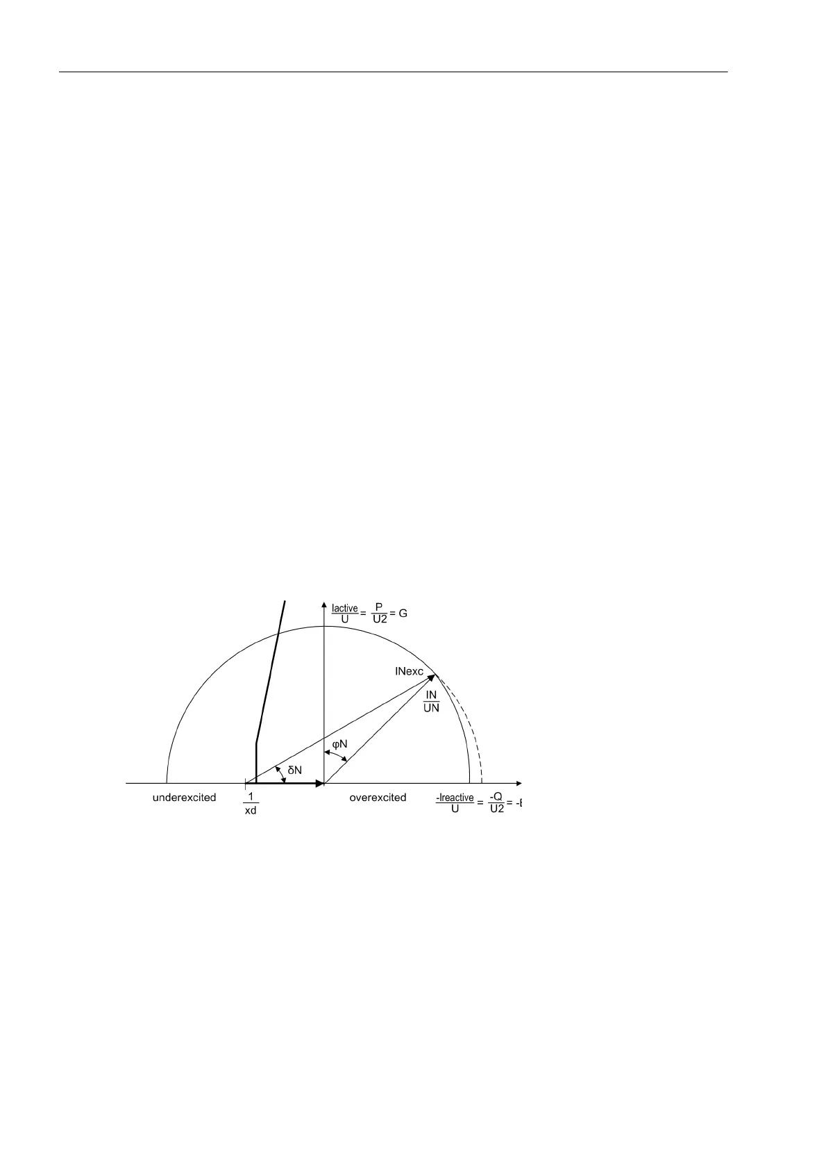
The following figure shows the loading diagram of the synchronous machine in the admittance plane (P/U
2
; –
Q/U
2
) with the static stability limit which crosses the reactive axis near 1/x
d
(reciprocal value of the synchronous
direct reactance).
Figure 2-53 Admittance Diagram of Turbo Generators
The underexcitation protection in the 7UM62 makes available three independent, freely combinable character-
istics. As illustrated in the following figure, it is possible for example to model static machine stability by means
of two partial characteristics with the same time delays (T CHAR. 1 = T CHAR 2). The partial characteristics
are distinguished by the corresponding distance from the zero point (1/xd CHAR. 1) and (1/xd CHAR. 2) as well
as the corresponding inclination angle α
1
and α
2
.
If the resulting characteristic (1/xd CHAR.1)/α
1
; (1/xd CHAR.2)/α
2
is exceeded (in the following figure on the
left), a delayed warning (e.g. by 10 s) or a trip signal is transmitted. The delay is necessary to ensure that the
voltage regulator is given enough time to increase the excitation voltage.

 Loading...


