Functions
2.43 Trip Circuit Supervision
SIPROTEC, 7UM62, Manual
C53000-G1176-C149-7, Release date 03.2010
300
Monitoring with One Binary Input
Note: When using only one binary input (BI) for the trip circuit monitor, some malfunctions, such as interruption
of the trip circuit or loss of battery voltage, can indeed be detected, but malfunctions with closed trip contacts
cannot. Therefore, the measurement must take place over a period of time that bridges the longest possible
duration of a closed trip contact. This is ensured by the fixed number of measurement repetitions and the time
between the condition checks.
When using only one binary input, a resistor R is inserted into the circuit on the system side, instead of the
missing second binary input. Through appropriate sizing of the resistor and depending on the system relation-
ship, a lower control voltage can often be sufficient. The resistor R is inserted into the circuit of the second circuit
breaker auxiliary contact (Aux2) to detect a malfunction also when the circuit breaker auxiliary contact (Aux1)
is open, and the trip contact has dropped out (see Figure „Principle of Trip Circuit Monitoring with One Binary
Input“). This resistor must be sized such that the circuit breaker trip coil (CBTC) is no longer energized when
the circuit breaker is open (which means Aux1 is open and Aux2 is closed). Binary input (BI1) should still be
picked up when the trip contact is simultaneously opened.
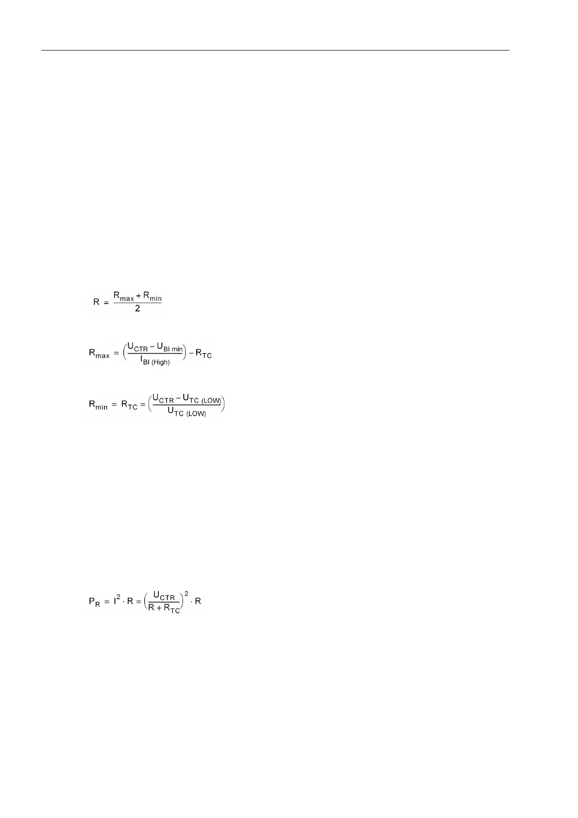
This results in an upper limit for the resistance R
max
, and a lower limit R
min
, from which the optimum value of
the arithmetic mean R should be selected:
In order that the minimum voltage for controlling the binary input is ensured, R
max
is derived as:
To keep the circuit breaker trip coil not energized in the above case, R
min
is derived as:
with
I
BI (HIGH)
Constant current with activated BI ( = 1.8 mA)
U
BI min
minimum control voltage for BI (19 V for delivery setting for nominal voltages 24/48/60 V; 88
V for delivery setting for nominal voltages 110/125/220/250 V)
U
CTR
Control Voltage for Trip Circuit
R
TC
DC resistance of circuit breaker trip coil
U
TC (LOW)
Maximum voltage on the circuit breaker trip coil that does not lead to tripping
If the calculation results in R
max
< R
min
, then the calculation must be repeated, with the next lowest switching
threshold U
BI min
, and this threshold must be implemented in the relay using plug-in jumper(s).
For power consumption of the resistance:

 Loading...


