Functions
2.15 Earth Current Differential Protection (ANSI 87GN,TN)
SIPROTEC, 7UM62, Manual
C53000-G1176-C149-7, Release date 03.2010
129
Measuring Principle
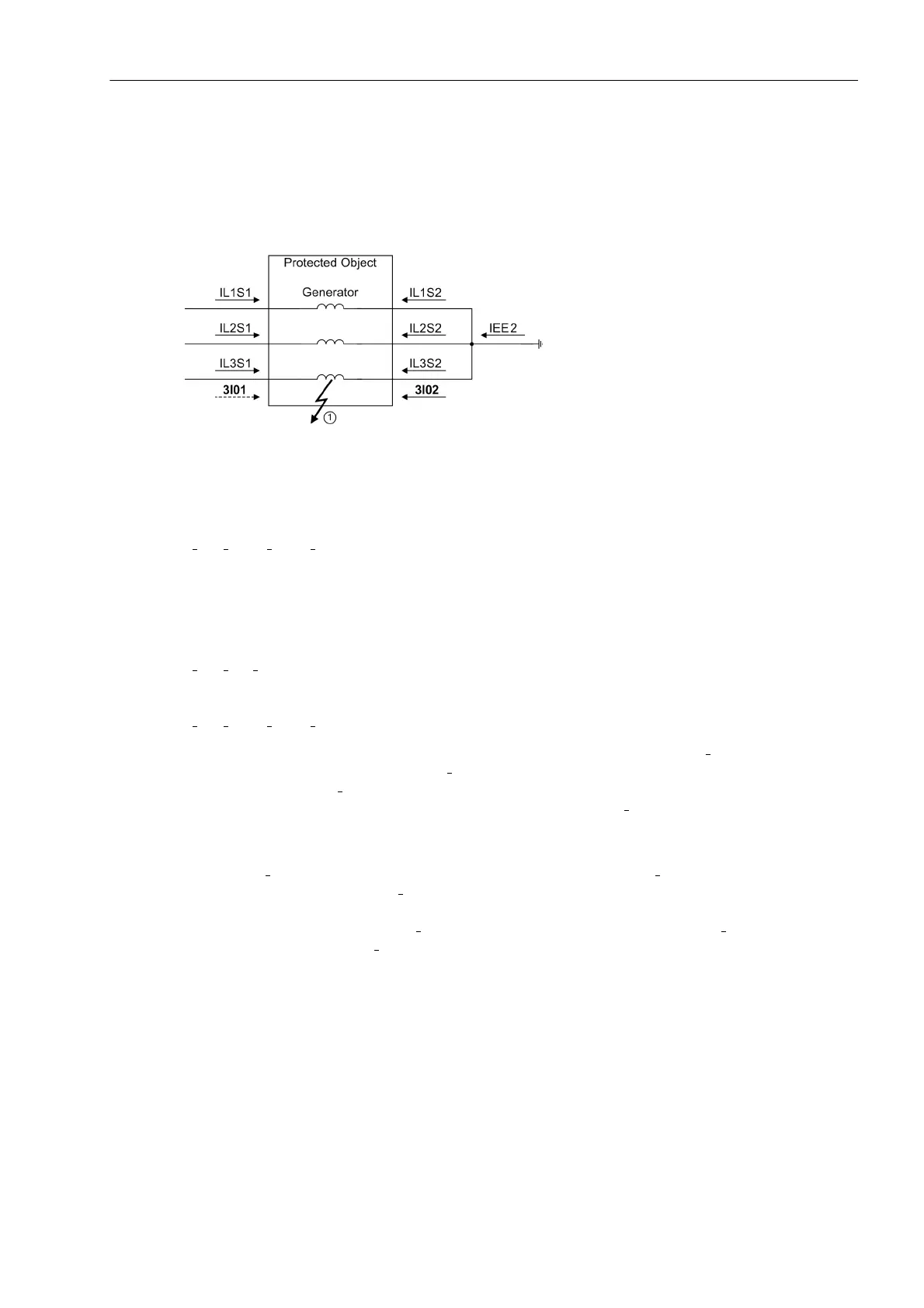
The 2 possible implementations of the earth fault differential protection differ only in their method of determining
the zero sequence current. This is shown in the following picture. This figure also shows the definition of the
current direction. The general definition is: Reference arrows run in positive direction to the protected object.
Figure 2-48 Connection scheme and definition of current vectors
In both measuring principles, there is a vector addition of the phase currents on the line side (always side 1 in
the 7UM62), which yields the zero sequence current. The rule of calculation for side 1 is:
3I
01
= I
L1S1
+ I
L2S1
+ I
L3S1
For the second zero sequence current, two methods of determination are possible:
On the one hand it is measured directly as the starpoint current at input I
EE2
(I
St
= I
EE2
). Method 2 is to calculate
the zero sequence current from the CTs on the starpoint side (always side 2 in the 7UM62). The pertinent for-
mulas are:
3I
02
= I
St
= I
EE2
or
3I
02
= I
L1S2
+ I
L2S2
+ I
L3S2
When an earth fault occurs in the protected zone, there is always a starpoint current I
St
or zero sequence
current flowing through the CTs of side 2 (3I
02
). Depending on the network earthing conditions, there may also
be an earthing current (3I
01
) flowing through the CTs of side 1 to the fault location (dashed arrow). Due to the
definition of the current direction, however, the zero sequence current 3I
01
is more or less in phase with the
starpoint current.
When an earth fault occurs outside the protected zone (see next picture, fault location 2), there is also a star-
point current I
St
or zero sequence current flowing through the CTs of side 2 (3I
02
) and a zero sequence current
flowing through the CTs of side 1 (3I
01
). The zero sequence current must be the same at all three possible mea-
surement locations. As the current direction flowing into the protected object is defined as positive, the zero
sequence current flowing on side 1 (3I
01
) is in phase opposition to the starpoint current I
St
or to the computed
zero phase current of side 2 (3I
02
).

 Loading...


