Mounting and Commissioning
3.2 Checking Connections
SIPROTEC, 7UM62, Manual
C53000-G1176-C149-7, Release date 03.2010
394
The accuracy which can be achieved during testing depends on the accuracy of the testing equipment. The
accuracy values specified in the Technical Data can only be reproduced under the reference conditions set
down in IEC 60 255 resp. VDE 0435/part 303 and with the use of precision measuring instruments.
Tests can be performed using the currently set values or the default values.
If unsymmetrical currents and voltages occur during the tests it is likely that the asymmetry monitoring will fre-
quently pickup. This is of no concern because the condition of steady-state measured values is monitored
which, under normal operating conditions, are symmetrical; under short circuit conditions these monitorings are
not effective.
Note
If during dynamic testing, measured values are connected from or reduced to zero, a sufficiently high value
should be present in at least one other measuring circuit (in general a voltage), to permit frequency adaptation.
Measured values in earth paths of voltage or current (I
EE
, U
E
) can not adapt the scanning frequency. To check
them, a sufficiently high value measured value must be present in at least one of the phases.
Secondary Test of the Differential Protection
A test set with 6 current outputs is recommended for secondary testing. The following section gives hints how
to proceed for testing with fewer current sources. The test current can be injected individually for each winding,
thus simulating each time a transformer fault with single-ended infeed.
For three or two-phase testing the parameter (address 2021) set for I-DIFF> is valid as the pickup value on
presetting. The pickup value for single-phase testing depends on how the zero sequence current is treated:
If the zero sequence current is eliminated, the pickup value increases to 1.5 times the set value; this corre-
sponds to conventional circuitry when current is fed in via matching transformers.
If the zero sequence current is not eliminated (isolated starpoint), the pickup current corresponds to the setting
value I-DIFF> even during single-phase testing.
Checking the pickup value is performed by slowly increasing the test current for each winding with the second-
ary test set. Tripping is initiated when the converted pickup value is reached. When the test current reaches
0.7 times the pickup value, the tripping command drops off.
In the method described above, the pickup values for single-ended infeed are tested in each case. It is also
possible to check the entire characteristic. Since trip current and restraint current cannot be fed in separately
(they can, however, be read out separately in the test measurements), a separate test current has to be applied
to each of the two windings.
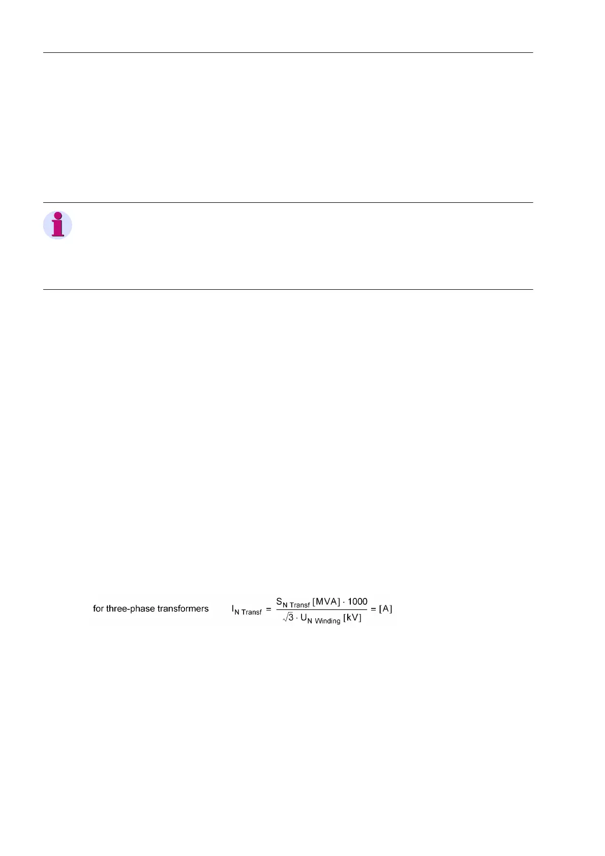
When testing with the operational parameters, it should be noted that the setting value I-DIFF> refers to the
rated current of the transformer, i.e. current which results from
with
S
N, Transf
Nominal apparent power of the transformer
U
N Winding
Rated voltage of the respective winding; for a winding with regulated volt-
age, the voltage computed in accordance with Section 2.14.1.2 applies
Furthermore, the pickup values can change with single and two-phase testing depending on the vector group
of the protected transformer; this corresponds to conventional circuitry, when currents are applied via matching
current transformers. Table 3-27 shows these changes as a factor k
VG
depending on the vector group and the
type of fault, for three-phase transformers.

 Loading...


